
Related Manuals for Festo MPS 404-1


Summary of Contents for Festo MPS 404-1
- Page 1 8150260 404-1 System Systems Operating instructions Betriebsanleitung Instrucciones de utilización Notice d'utilisation Festo Didactic 8150266 en/de/es/fr 12/2020...
- Page 2 Revision level: 12/2020 Authors: Festo Didactic Layout: Festo Didactic © Festo Didactic SE, Rechbergstraße 3, 73770 Denkendorf, Germany, 2020 +49 711 3467-0 www.festo-didactic.com +49 711 34754-88500 did@festo.com Translation of the original operating instructions Reproduction, distribution and utilisation of this document, as well as the communication of its contents to others without explicit authorisation, is prohibited.
- Page 3 Lesbarkeit und dem besseren Verständnis der Formulierungen. VORSICHT Diese Betriebsanleitung muss dem Anwender ständig zur Verfügung stehen. Vor Inbetriebnahme muss die Betriebsanleitung gelesen werden. Die Sicherheitshinweise müssen beachtet werden. Bei Missachten kann es zu schweren Personen- oder Sachschäden kommen. © Festo Didactic 8150266...
- Page 4 Les instructions de service doivent être constamment à la disposition de l'utilisateur. Les instructions de service doivent avoir été lues avant la mise en service. Se conformer aux consignes de sécurité. Le non-respect peut entraîner de graves dommages corporels ou matériels. © Festo Didactic 8150266...
-
Page 5: Table Of Contents
Scope of delivery __________________________________________________________________ 32 Configuration ____________________________________________________________________ 33 The MPS system 404-1 _____________________________________________________________ 33 The Distributing Pro station _________________________________________________________ 34 The Joining station ________________________________________________________________ 36 The Measuring Pro station __________________________________________________________ 38 The Sorting Inline station ___________________________________________________________ 40 © Festo Didactic 8150266... - Page 6 Establishing 1-bit communication links ________________________________________________ 52 12.6 Workstation ______________________________________________________________________ 52 12.7 Power supply _____________________________________________________________________ 53 12.8 Loading PLC programs _____________________________________________________________ 53 Accessories ______________________________________________________________________ 53 Maintenance and cleaning _________________________________________________________ 54 Further information and updates ____________________________________________________ 54 Disposal ________________________________________________________________________ 54 © Festo Didactic 8150266...
-
Page 7: General Requirements For Operating The Devices
Damaged devices must be banned from further use and removed from the laboratory or classroom. – Damaged connecting cables, pneumatic tubing and hydraulic hoses represent a safety risk and must be removed from the laboratory or classroom. © Festo Didactic 8150266... -
Page 8: Safety Instructions And Pictograms
... indicates a possibly hazardous situation which may result in moderate or slight personal injury or severe property damage if not avoided. NOTICE ... indicates a possibly hazardous situation which may result in property damage or loss of function if not avoided. © Festo Didactic 8150266... -
Page 9: Pictograms
404-1 System, Distributing Pro-Joining-Measuring Pro-Sorting Inline – Operating instructions 2.2 Pictograms Warning regarding of a danger point Warning regarding dangerous electric voltage Warning regarding hand injuries Warning regarding entanglement hazard Information and/or references to other documentation © Festo Didactic 8150266... -
Page 10: Use For Intended Purpose
Festo Didactic hereby excludes any and all liability for damages suffered by trainees, the training company and/or any third parties, which occur during use of the device in situations which serve any purpose other than training and/or vocational education, unless such damages have been caused by Festo Didactic due to malicious intent or gross negligence. -
Page 11: For Your Safety
Knowledge of the basic safety instructions and safety regulations is a fundamental prerequisite for safe handling and trouble-free operation of Festo Didactic components and systems. These operating instructions include the most important instructions for safe use of the components and systems. -
Page 12: Obligations Of The Operating Company
All persons who have been entrusted to work with the components and systems undertake to complete the following steps before beginning work: • Read the chapter concerning safety and the warnings in these operating instructions. • Familiarize themselves with the basic regulations regarding work safety and accident prevention. © Festo Didactic 8150266... -
Page 13: Work And Safety Instructions
Mount all of the components securely on the profile plate. • Make sure that limit valves are not actuated from the front. • Set all components up so that it’s easy to activate the switches and interrupters. • Follow the instructions about positioning the components. © Festo Didactic 8150266... -
Page 14: Electrical Safety
Further information on this issue is available in the data sheets and operating instructions included with the components. Caution! – Capacitors inside the device may still be charged even after being disconnected from all sources of voltage. © Festo Didactic 8150266... - Page 15 Hazard-free operation of the device is no longer possible in the case of: – Visible damage – Malfunction – Incorrect storage – Incorrect transport – Switch off the power supply immediately. – Protect the device against inadvertent restart. © Festo Didactic 8150266...
-
Page 16: Pneumatic Safety
Do not switch on the compressed air until all the tubing connections have been established and secured. • Do not disconnect pneumatic tubing while under pressure. – Do not attempt to connect pneumatic tubing or push-in connectors with your hands or fingers. © Festo Didactic 8150266... - Page 17 Reduce noise by using pneumatic mufflers, or wear hearing protection if noise cannot be avoided. – All of the exhaust ports of the components included in the equipment sets are equipped with mufflers. Do not remove these mufflers. © Festo Didactic 8150266...
-
Page 18: Safety Sockets
The circuit design may contain additional safety sockets due to the use of different components. The specified protection class and safe use can only be assured if laboratory safety cables supplied by Festo Didactic are used. © Festo Didactic 8150266... - Page 19 1.5 mm socket head screw. The detent is located in the drilled hole of the adapter. Unscrew the screw in clockwise direction. WARNING Danger of electric shock! Damaged safety laboratory cables must be blocked immediately and removed from the laboratory area! © Festo Didactic 8150266...
-
Page 20: Technical Data
Electrical connection Standard power plug RJ-45 network connection Pneumatic connection Plastic tubing with 6 mm outside diameter Compressed air consumption at 600 kPa (continuous cycle) 10 l/min. Dimensions 2100 x 700 x 1705 mm Subject to change © Festo Didactic 8150266... -
Page 21: Terminal Assignment Table For Distributing Pro Station
24 V B 21+22 White-pink 24 V supply for inputs GND A Brown-pink 0 V power supply for outputs GND A Purple 0 V power supply for outputs GND B 23+24 White-blue 0 V supply for inputs © Festo Didactic 8150266... - Page 22 24 V B 21+22 White-pink 24 V supply for inputs GND A Brown-pink 0 V power supply for outputs GND A Purple 0 V power supply for outputs GND B 23+24 White-blue 0 V supply for inputs © Festo Didactic 8150266...
- Page 23 GND A Purple 0 V power supply for outputs GND B 23+24 White-blue 0 V power supply for inputs Cable jumpers are connected from emergency stop to bit 1.5 for all PLC EduTrainer universal standard MPS versions. © Festo Didactic 8150266...
-
Page 24: Terminal Assignment Table, Joining Station
23+24 White-blue 0 V power supply for inputs Analog Function D-SUB-15 Color Designation Workpiece orientation not correct, analog Cable jumpers are connected from emergency stop to bit 1.5 for all PLC EduTrainer universal standard MPS versions. © Festo Didactic 8150266... - Page 25 In the case of XG2, all signals are transmitted via a bus node, which addresses the signals with different protocols depending on the controller. • With a Siemens PLC: ProfiNet, • with an Allen Bradley PLC: Ethernet IP © Festo Didactic 8150266...
-
Page 26: Pin Allocation Table For The Measuring Pro Station
White-blue 0 V power supply for inputs Analog Function D-SUB-15 Color Designation Yellow-white Analog input, measured value scales Cable jumpers are connected from emergency stop to bit 1.5 for all PLC EduTrainer universal standard MPS versions. © Festo Didactic 8150266... - Page 27 24 V B 21+22 White-pink 24 V supply for inputs GND A Brown-pink 0 V power supply for outputs GND A Purple 0 V power supply for outputs GND B 23+24 White-blue 0 V supply for inputs © Festo Didactic 8150266...
- Page 28 24 V B 21+22 White-pink 24 V supply for inputs GND A Brown-pink 0 V power supply for outputs GND A Purple 0 V power supply for outputs GND B 23+24 White-blue 0 V power supply for inputs © Festo Didactic 8150266...
- Page 29 In the case of IO link, all signals are transmitted via an IO link multi protocol module, which addresses the signals with different protocols depending on the controller. • Siemens PLC: ProfiNet, • Allen Bradley PLC: Ethernet IP, • Codesys PLC: IO link © Festo Didactic 8150266...
-
Page 30: Terminal Assignment Table For Sorting Inline
In the case of the MPS system 404-1 with Siemens controllers, the controllers, the PROFINET bus node, and the RFID gateways are connected to each other via three 8-port switches. These switches are found at the rear in the respective stations in the carriage. © Festo Didactic 8150266... - Page 31 404-1 System, Distributing Pro-Joining-Measuring Pro-Sorting Inline – Operating instructions RFID data transmission line Siemens SIMATIC S7-1500 PROFINET cable 5-port switch RFID write/read head PC for MES RFID gateway with RFID module PROFINET bus node © Festo Didactic 8150266...
-
Page 32: Transport, Unpacking, Scope Of Delivery
The crate may only be transported with a suitable pallet jack or forklift. The crate must be secured against tipping over and falling. – Report transport damage without delay to the freight forwarder and Festo Didactic. 8.2 Unpacking Carefully remove the padding material from the crate when unpacking the system or station. When unpacking the system or station, make sure that none of its assemblies have been damaged. -
Page 33: Configuration
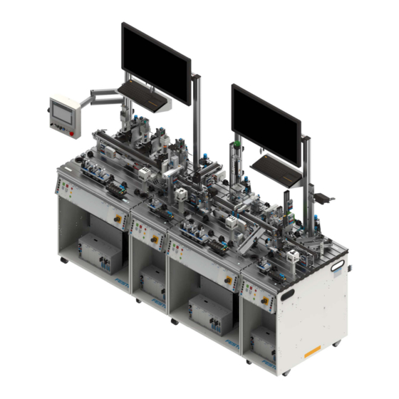
The MPS system 404-1 addresses, among other things, the topics of intelligent networking of machines and sequences using the example of a miniaturized production line. The system consists of four slightly adjusted standard stations: Distributing Pro, Measuring Pro, Joining, and Sorting Inline. © Festo Didactic 8150266... -
Page 34: The Distributing Pro Station
After the workpiece base has been pushed out of the stacking magazine module, the RFID read/write head writes the work order number, the position number and the functions to the RFID tag in the workpiece base. © Festo Didactic 8150266... - Page 35 For additional information, please see the following document: Distributing Pro station, document no. 8128256 You can find this document on the internet at the following address: www.ip.festo-didactic.com © Festo Didactic 8150266...
-
Page 36: The Joining Station
Microcontroller workpiece caps can be mounted on the MPS workpiece bases with the Joining station. You can use a mounting kit (order no. 8064882) for this, in order to switch over from a suction cup to a parallel gripper with gripper jaws. © Festo Didactic 8150266... - Page 37 The station has been expanded for the MPS System 404-1 Industry 4.0 to include the RFID module. For additional information, please see the following document: Joining station, document no. 8065303 You can find this document on the internet at the following address: www.ip.festo-didactic.com © Festo Didactic 8150266...
-
Page 38: The Measuring Pro Station
Following evaluation, the workpiece is transported back to the belt by the rotary lifting cylinder. Depending on the result the workpieces are either transported to the end of the belt or ejected onto a slide with filling level monitoring. © Festo Didactic 8150266... - Page 39 Checking or measuring position • Checking or measuring orientation For additional information, please see the following document: Measuring Pro station, document no. 8136944 You can find this document on the internet at the following address: www.ip.festo-didactic.com © Festo Didactic 8150266...
-
Page 40: The Sorting Inline Station
Sort workpieces according to their characteristics • Sort workpieces according to RFID tag content For additional information, please see the following document: Sorting Inline station, document no. 8129442 You can find this document on the internet at the following address: www.ip.festo-didactic.com © Festo Didactic 8150266... -
Page 41: The Siemens Tp700 Hmi
Displaying signal states • Operating actuators • Operating the station • Reading the parameter data of the IO-Link sensors • Setting the parameters of the IO-Link sensors • Setting the runtime monitoring for the push-out cylinders © Festo Didactic 8150266... -
Page 42: Web Interface With Raspberry Pi
Target or limit values for the weight transmitted by the MES. Graphical representation of the upper limit value. Graphical representation of the lower limit value. Status information on the measurement procedures. Graphical representation of the lower limit value. Graphical representation of the upper limit value. © Festo Didactic 8150266... -
Page 43: Mes
ONo and OPos is sent to the central MES system. The MES system then sends parameters for the work steps to the station that sent the query. A description of the MES software can be found in the Festo Didactic InfoPortal. www.ip.festo-didactic.com The software is normally required for all parts of the MPS system 404-1. -
Page 44: Io-Link Sensors
Optical distance sensor: exact value 1-7 (analog) • Ultrasonic sensor: exact value 1-7 (analog) • Capacitive sensor: level limit empty (x=0)*, half full (0<x<4), full (x>3) * Only detectable in combination with a light barrier in the magazine © Festo Didactic 8150266... -
Page 45: Function
Left: red workpieces; center: black workpieces; right: silver workpieces • No workpieces in the system's material flow process. • All stations in initial position and started up. 11.2 Initial position • Belt motors off at the stations • Stopper advanced • Chutes not full © Festo Didactic 8150266... -
Page 46: Resetting
11. The workpiece is detected at the start of the Joining station’s conveyor belt. 12. Distributing Pro station conveyor motor off. 13. The workpiece is stopped at the Joining station’s first RFID write/read head for reading/writing. 14. The RFID tag is read. © Festo Didactic 8150266... - Page 47 40. The workpiece is detected at the end of the first conveyor. 41. Measuring Pro station motor on. 42. Workpiece is detected at the start of the Measuring Pro station’s conveyor. 43. Joining station conveyor motor off. 44. Workpiece in downstream station. © Festo Didactic 8150266...
- Page 48 58. The workpiece is transported to the end of the conveyor or to the next station. 59. Sorting Inline station motor on. 60. The workpiece is stopped at the Sorting Inline station’s first RFID write/read head for reading/writing. 61. Measuring Pro station conveyor motor off. © Festo Didactic 8150266...
- Page 49 STOP button at the control panel after the end of a cycle. • The following applies when several stations are combined: The individual stations are aligned in the reverse order to the flow of materials. © Festo Didactic 8150266...
-
Page 50: Commissioning
Setup as individual station, Setup with downstream station, the stopper at the end of the conveyor is mounted the stopper at the end of the conveyor is removed © Festo Didactic 8150266... -
Page 51: Pneumatic Commissioning
If the cable length from the distributor block needs to be increased, this can only be carried out by appropriately trained, skilled personnel. The plug socket used must be fused appropriately for the consuming devices. In order to avoid problems during operation, individual fusing (16 A) of the system is strongly recommended. © Festo Didactic 8150266... -
Page 52: Establishing 1-Bit Communication Links
You will require the following items in order to commission the MPS system with the sample programs: • Dust-free laboratory environment • Compressed air supply: 600 kPa (6 bar) • A PC with installed PLC programming software © Festo Didactic 8150266... -
Page 53: Power Supply
PE+ protective grounding connecting cable, assortment comprising: 8x PE+ cables, 100 mm; 4x PE+ cables, 400 mm; 4x PE+ cables, 1500 mm, order no.: 8067503 • PE+ adapter set, 4 mm to PE+, assembly instructions and tools, order no.: 8067500 © Festo Didactic 8150266... -
Page 54: Maintenance And Cleaning
404-1 System, Distributing Pro-Joining-Measuring Pro-Sorting Inline – Operating instructions 14 Maintenance and cleaning Festo Didactic systems and components are to a great extent maintenance free. The following components should be cleaned at regular intervals with a soft, lint-free cloth or brush: •... - Page 55 Auspacken _______________________________________________________________________ 82 Lieferumfang _____________________________________________________________________ 82 Aufbau __________________________________________________________________________ 83 Das MPS System 404-1 _____________________________________________________________ 83 Die Station Verteilen Pro ___________________________________________________________ 84 Die Station Fügen _________________________________________________________________ 86 Die Station Messen Pro ____________________________________________________________ 88 Die Station Sortieren Inline _________________________________________________________ 90 © Festo Didactic 8150266...
- Page 56 1-Bit Kommunikationsverbindungen herstellen ________________________________________ 102 12.6 Arbeitsplatz _____________________________________________________________________ 102 12.7 Spannungsversorgung ____________________________________________________________ 103 12.8 SPS Programme laden ____________________________________________________________ 103 Zubehör ________________________________________________________________________ 103 Wartung und Reinigung ___________________________________________________________ 104 Weitere Informationen und Aktualisierungen _________________________________________ 104 Entsorgung _____________________________________________________________________ 104 © Festo Didactic 8150266...
-
Page 57: Allgemeine Voraussetzungen Zum Betreiben Der Geräte
Es dürfen keine Geräte mit Schäden oder Mängeln verwendet werden. – Schadhafte Geräte sind zu sperren und aus dem Labor- oder Unterrichtsraum zu entfernen. – Beschädigte Verbindungsleitungen, Druckluftschläuche und Hydraulikschläuche stellen ein Sicherheitsrisiko dar und müssen aus dem Labor- oder Unterrichtsraum entfernt werden. © Festo Didactic 8150266... -
Page 58: Sicherheitshinweise Und Piktogramme
… weist auf eine möglicherweise gefährliche Situation hin, die zu mittleren und leichten Körperverletzungen oder zu schwerem Sachschaden führen kann, wenn sie nicht vermieden wird. HINWEIS … weist auf eine möglicherweise gefährliche Situation hin, die zu Sachschaden oder Funktionsverlust führen kann, wenn sie nicht vermieden wird. © Festo Didactic 8150266... -
Page 59: Piktogramme
System 404-1, Verteilen Pro-Fügen-Messen Pro-Sortieren Inline 2.2 Piktogramme Warnung vor einer Gefahrenstelle Warnung vor gefährlicher elektrischer Spannung Warnung vor Handverletzungen Warnung vor Einzugsgefahr Informationen und/oder Verweise auf andere Dokumentationen © Festo Didactic 8150266... -
Page 60: Bestimmungsgemäße Verwendung
Regeln gebaut. Dennoch können bei unsachgemäßer Verwendung Gefahren für Leib und Leben des Benutzers oder Dritter und Beeinträchtigungen der Komponenten entstehen. Das Lernsystem von Festo Didactic ist ausschließlich für die Aus- und Weiterbildung im Bereich Automatisierung und Technik entwickelt und hergestellt. Das Ausbildungsunternehmen und/oder die Ausbildenden hat/haben dafür Sorge zu tragen, dass die Auszubildenden die Sicherheitsvorkehrungen, die... -
Page 61: Für Ihre Sicherheit
4 Für Ihre Sicherheit 4.1 Wichtige Hinweise Grundvoraussetzung für den sicherheitsgerechten Umgang und den störungsfreien Betrieb der Komponenten und Systeme von Festo Didactic ist die Kenntnis der grundlegenden Sicherheitshinweise und der Sicherheitsvorschriften. Diese Betriebsanleitung enthält die wichtigsten Hinweise, um die Komponenten und Systeme sicherheitsgerecht zu betreiben. -
Page 62: Verpflichtung Des Betreibers
Alle Personen, die mit Arbeiten an den Komponenten und Systemen beauftragt sind, verpflichten sich, vor Arbeitsbeginn: • das Sicherheitskapitel und die Warnhinweise in dieser Betriebsanleitung zu lesen, • die grundlegenden Vorschriften über Arbeitssicherheit und Unfallverhütung zu beachten. © Festo Didactic 8150266... -
Page 63: Arbeits- Und Sicherheitshinweise
Montieren Sie alle Komponenten fest auf die Profilplatte. • Stellen Sie sicher, dass Grenztaster nicht frontal betätigt werden. • Stellen Sie alle Komponenten so auf, dass das Betätigen von Schaltern und Trenneinrichtungen nicht erschwert wird. • Beachten Sie Angaben zur Platzierung der Komponenten. © Festo Didactic 8150266... -
Page 64: Elektrik
Beachten Sie, dass elektrische Energie in einzelnen Komponenten gespeichert sein kann. Informationen hierzu finden Sie in den Datenblättern und Betriebsanleitungen der Komponenten. – Warnung! Kondensatoren im Gerät können noch geladen sein, selbst wenn das Gerät von allen Spannungsquellen getrennt wurde. © Festo Didactic 8150266... - Page 65 Ein gefahrloser Betrieb des Geräts ist nicht mehr möglich bei – sichtbarer Beschädigung, – defekter Funktion, – unsachgemäßer Lagerung oder – unsachgemäßem Transport. – Schalten Sie sofort die Spannung ab. – Schützen Sie das Gerät vor unbeabsichtigtem Wiedereinschalten. © Festo Didactic 8150266...
-
Page 66: Pneumatik
Schalten Sie die Druckluft erst ein, wenn Sie alle Schlauchverbindungen hergestellt und gesichert haben. • Entkuppeln Sie keine Schläuche unter Druck. – Versuchen Sie nicht, Schläuche oder Steckverbindungen mit den Fingern oder der Hand zu verschließen. © Festo Didactic 8150266... - Page 67 Reduzieren Sie den Lärm durch den Einsatz von Schalldämpfern oder tragen Sie einen Gehörschutz, falls der Lärm sich nicht vermeiden lässt. – Alle Abluftanschlüsse der Komponenten der Gerätesätze sind mit Schalldämpfern versehen. Entfernen Sie diese Schalldämpfer nicht. © Festo Didactic 8150266...
-
Page 68: Sicherheitssteckbuchsen
Die Komponente enthält möglicherweise nicht alle der oben dargestellten Sicherheitssteckbuchsen. Im Schaltungsaufbau können durch die Verwendung verschiedener Komponenten weitere Sicherheitssteckbuchsen enthalten sein. Die angegebenen Schutzklassen und die Sicherheit werden bei Verwendung von Festo Didactic Sicherheits- Laborleitungen erreicht. © Festo Didactic 8150266... - Page 69 In Verantwortung des Betreibers kann dieser Adapter entfernt werden. Mit einem 1,5 mm Inbusschlüssel kann der Adapter gelöst werden. Die Arretierung befindet sich in der Bohrung des Adapters. Die Schraube wird rechtsdrehend gelöst. WARNUNG Gefahr durch Stromschlag! Schadhafte Sicherheits-Laborleitungen sind sofort zu sperren und aus dem Prüfbereich zu entfernen! © Festo Didactic 8150266...
-
Page 70: Technische Daten
Ausgänge: max. 2 A gesamt Elektrischer Anschluss Schutzkontakt Stecker RJ-45 Netzwerkanschluss Pneumatischer Anschluss Kunststoffschlauch mit 6 mm Außendurchmesser Druckluftverbrauch bei 600 kPa (Dauerzyklus) 10 l/min Maße 1400 mm x 700 mm x 1705 mm Änderungen vorbehalten © Festo Didactic 8150266... -
Page 71: Kontaktbelegungstabelle Station Verteilen Pro
24 V Versorgung der Ausgänge 24 V B 21+22 weiß-rosa 24 V Versorgung der Eingänge GND A braun-rosa 0 V Versorgung der Ausgänge GND A lila 0 V Versorgung der Ausgänge GND B 23+24 weiß-blau 0 V Versorgung der Eingänge © Festo Didactic 8150266... - Page 72 24 V Versorgung der Ausgänge 24 V B 21+22 weiß-rosa 24 V Versorgung der Eingänge GND A braun-rosa 0 V Versorgung der Ausgänge GND A lila 0 V Versorgung der Ausgänge GND B 23+24 weiß-blau 0 V Versorgung der Eingänge © Festo Didactic 8150266...
- Page 73 0 V Versorgung der Ausgänge GND A lila 0 V Versorgung der Ausgänge GND B 23+24 weiß-blau 0 V Versorgung der Eingänge Bei allen SPS EduTrainer Universal Vorzugsvarianten MPS sind Kabelbrücken von NOT-HALT auf Bit 1.5 gesteckt. © Festo Didactic 8150266...
-
Page 74: Kontaktbelegungstabelle Station Fügen
0 V Versorgung der Ausgänge GND B 23+24 weiß-blau 0 V Versorgung der Eingänge Analog Funktion D-SUB-15 Farbe Benennung Werkstückorientierung nicht korrekt, analog Bei allen SPS EduTrainer Universal Vorzugsvarianten MPS sind Kabelbrücken von NOT-HALT auf Bit 1.5 gesteckt. © Festo Didactic 8150266... - Page 75 Bei XG2 laufen alle Signale über einen Busknoten, bei dem die Signale – je nach Steuerung – mit einem anderen Protokoll angesprochen werden. • Bei einer Siemens SPS: ProfiNet, • bei einer Allen Bradley SPS: Ethernet IP © Festo Didactic 8150266...
-
Page 76: Kontaktbelegungstabelle Station Messen Pro
0V Versorgung der Ausgänge GND B 23+24 weiß-blau 0V Versorgung der Eingänge Analog Funktion Sub D 15 Farbe Benennung Gelb-weiß Messwert Waage Bei allen SPS EduTrainer Universal Vorzugsvarianten MPS sind Kabelbrücken von NOT-HALT auf Bit 1.5 gesteckt. © Festo Didactic 8150266... - Page 77 24 V Versorgung der Ausgänge 24 V B 21+22 weiß-rosa 24 V Versorgung der Eingänge GND A braun-rosa 0V Versorgung der Ausgänge GND A lila 0V Versorgung der Ausgänge GND B 23+24 weiß-blau 0V Versorgung der Eingänge © Festo Didactic 8150266...
- Page 78 24 V Versorgung der Ausgänge 24 V B 21+22 weiß-rosa 24 V Versorgung der Eingänge GND A braun-rosa 0V Versorgung der Ausgänge GND A lila 0V Versorgung der Ausgänge GND B 23+24 weiß-blau 0V Versorgung der Eingänge © Festo Didactic 8150266...
- Page 79 Bei IO-Link laufen alle Signale über ein IO-Link Multiprotokoll Modul, bei dem die Signale – je nach Steuerung – mit einem anderen Protokoll angesprochen werden. • Siemens SPS: ProfiNet, • Allen Bradley SPS: Ethernet IP, • Codesys SPS: IO-Link © Festo Didactic 8150266...
-
Page 80: Kontaktbelegungstabelle Station Sortieren Inline
7.6 Vernetzung des Systems Bei dem MPS System 404-1 mit Siemens Steuerungen sind die Steuerungen, der PROFINET Busknoten und die RFID Gateways über drei 8-Port Switches miteinander verbunden. Diese Switches befinden sich hinten in den jeweiligen Stationen im Wagen. © Festo Didactic 8150266... - Page 81 System 404-1, Verteilen Pro-Fügen-Messen Pro-Sortieren Inline RFID Datenleitung Siemens SIMATIC S7-1500 PROFINET Leitung 5-Port Switch RFID Schreib-/Lesekopf PC für MES System RFID Gateway mit RFID Modul PROFINET Busknoten © Festo Didactic 8150266...
-
Page 82: Transport/Auspacken/Lieferumfang
Transportieren Sie die Transportbox ausschließlich mit geeigneten Hubwagen oder Gabelstaplern. Sichern Sie die Transportbox gegen Umfallen und Herunterfallen. – Melden Sie Transportschäden unverzüglich dem Spediteur und Festo Didactic. 8.2 Auspacken Entfernen Sie beim Auspacken des Systems oder der Station vorsichtig das Füllmaterial aus der Transportbox. -
Page 83: Aufbau
Anordnungen möglich sind. Das MPS System 404-1 thematisiert unter anderem die intelligente Vernetzung von Maschinen und Abläufen am Beispiel einer miniaturisierten Fertigungsstraße. Das System besteht aus vier leicht angepassten Standardstationen: Verteilen Pro, Fügen, Messen Pro und Sortieren Inline. © Festo Didactic 8150266... -
Page 84: Die Station Verteilen Pro
Zusätzlich sind IO-Link Sensoren zur Füllstandserfassung der Magazine, Taster zur De-Aktivierung der einzelnen Stapelmagazine und ein Modul RFID integriert. Nachdem ein Werkstückkörper aus dem Modul Stapelmagazin ausgeschoben wurde, schreibt der RFID Schreib-/Lesekopf die Auftragsnummer, die Positionsnummer sowie Funktionen auf den RFID Tag im Werkstückkörper. © Festo Didactic 8150266... - Page 85 MES System gesendet. Das MES System sendet dann Parameter für die Arbeitsschritte an die anfragende Station. Zusätzliche Informationen entnehmen Sie bitte auch dem folgenden Dokument: Station Verteilen Pro, Dokument-Nr. 8128256 Sie finden dieses Dokument im Internet unter folgender Adresse: www.ip.festo-didactic.com © Festo Didactic 8150266...
-
Page 86: Die Station Fügen
Werkstückdeckel auf die MPS Werkstückkörper zu fügen Mit der Station Fügen ist es möglich, µController-Werkstückdeckel auf die MPS Werkstückkörper zu fügen. Hierfür können Sie einen Anbausatz ( Bestell-Nr. 8064882) nutzen, um vom Vakuumsauger auf einen Parallelgreifer mit Greifbacken umzurüsten. © Festo Didactic 8150266... - Page 87 Die Station wurde für das MPS System 404-1 mit dem Modul RFID erweitert. Zusätzliche Informationen entnehmen Sie bitte auch dem folgenden Dokument: Station Fügen, Dokument-Nr. 8065303 Sie finden dieses Dokument im Internet unter folgender Adresse: www.ip.festo-didactic.com © Festo Didactic 8150266...
-
Page 88: Die Station Messen Pro
Station vorhandene Waage (realisiert mit Wägezelle) kann das genaue Gewicht der Werkstücke erfassen. Nach Auswertung wird das Werkstück durch den Dreh-Hub Zylinder wieder dem Band zugeführt. Je nach Ergebnis werden die Werkstücke an das Bandende transportiert oder auf eine Rutsche mit Füllstandüberwachung ausgeschleust. © Festo Didactic 8150266... - Page 89 Größe prüfen oder messen • Position prüfen oder messen • Orientierung prüfen oder messen. Zusätzliche Informationen entnehmen Sie bitte auch dem folgenden Dokument: Station Messen Pro, Dokument-Nr. 8136944 Sie finden dieses Dokument im Internet unter folgender Adresse: www.ip.festo-didactic.com © Festo Didactic 8150266...
-
Page 90: Die Station Sortieren Inline
Werkstücke nach Beschaffenheit zu sortieren • Werkstücke nach Inhalt des RFID Tags zu sortieren Zusätzliche Informationen entnehmen Sie bitte auch dem folgenden Dokument: Station Sortieren Inline, Dokument-Nr. 8129442 Sie finden dieses Dokument im Internet unter folgender Adresse: www.ip.festo-didactic.com © Festo Didactic 8150266... -
Page 91: Das Hmi Siemens Tp700
Die Aufgaben des HMI sind • Anzeigen vom Magazinfüllständen • Anzeigen von Signalzuständen • Bedienen von Aktoren • Bedienen der Station • Auslesen von Parameterdaten der IO-Link Sensoren • Parametrieren der IO-Link Sensoren • Einstellung der Laufzeitüberwachung der Ausschiebezylinder © Festo Didactic 8150266... -
Page 92: Weboberfläche Mit Raspberry-Pi
Von der Station ermitteltes Gewicht. Dieses wird ans MES übertragen. Vom MES übermittelte Soll- bzw. Grenzwerte des Gewichts. Grafische Darstellung des oberen Grenzwerts. Grafische Darstellung des unteren Grenzwerts. Status Informationen zu den Messvorgängen. Grafische Darstellung des unteren Grenzwerts. Grafische Darstellung des oberen Grenzwerts. © Festo Didactic 8150266... -
Page 93: Mes
Nach dem Auslesen wird mit der jeweiligen ONo und OPos eine Anfrage an das zentrale MES System gesendet. Das MES System sendet dann Parameter für die Arbeitsschritte an die anfragende Station. Eine Beschreibung der MES-Software finden Sie im Festo Didactic InfoPortal. www.ip.festo-didactic.com Die Software wird generell bei dem MPS System 404-1 benötigt. -
Page 94: Io-Link Sensoren
Stapelmagazin können in Kombination mit der Lichtschranke den Füllstand angeben: • Optische Abstandsensor: genauen Wert 1-7 (analog) • Ultraschallsensor: genauen Wert 1-7 (analog) • Kapazitive Sensor: Füllstandsgrenze leer (x=0)*, halbvoll (0<x<4), voll (x>3) * nur in Verbindung mit Lichtschranke im Magazin detektierbar © Festo Didactic 8150266... -
Page 95: Funktion
Werkstücke; mittig: schwarze Werkstücke; rechts: silberne Werkstücke • Keine Werkstücke im Materialfluss des Systems. • Alle Stationen in Ausgangsstellung und gestartet. 11.2 Ausgangsstellung • Bandmotoren der Stationen aus • Stopper ausgefahren • Rutschen nicht voll © Festo Didactic 8150266... -
Page 96: Richten
9. Werkstückerkennung in der Station Fügen. 10. Bandmotor Station Fügen ein. 11. Werkstückerkennung bei Bandanfang Station Fügen. 12. Bandmotor Station Verteilen Pro aus. 13. Werkstück hält zum Lesen/Schreiben am ersten RFID Schreib-/Lesekopf bei Station Fügen. 14. RFID Tag wird ausgelesen. © Festo Didactic 8150266... - Page 97 38. Weiche fährt ein. 39. Bandmotor Station Fügen ein. 40. Werkstückerkennung bei Bandende erstes Band. 41. Bandmotor Station Messen Pro ein. 42. Werkstückerkennung bei Bandanfang Station Messen Pro. 43. Bandmotor Station Fügen aus. 44. Werkstück in Folgestation. © Festo Didactic 8150266...
- Page 98 Fall 1: Messergebnis(se) korrekt. 58. Das Werkstück wird zum Bandende bzw. zur Folgestation transportiert. 59. Bandmotor Station Sortieren Inline ein 60. Werkstück hält zum Lesen/Schreiben am ersten RFID Schreib-/Lesekopf bei Station Sortieren Inline 61. Bandmotor Station Messen Pro aus © Festo Didactic 8150266...
- Page 99 Der Ablauf kann jederzeit durch Drücken des schwarzen rastenden STOP Tasters oder durch Drücken des roten STOP Tasters im Bedienfeld nach dem Zyklus unterbrochen werden. • Bei einer Kombination mehrerer Stationen gilt: Richten der einzelnen Stationen erfolgt entgegen dem Materialfluss. © Festo Didactic 8150266...
-
Page 100: Inbetriebnahme
Werden die Stationen Verteilen Pro und Fügen mit Folgestationen betrieben, müssen die Stopper am Ende des Moduls Band demontiert werden. Aufbau als Einzelstation, Aufbau mit Folgestation, der Stopper am Bandende ist montiert der Stopper am Bandende ist demontiert © Festo Didactic 8150266... -
Page 101: Pneumatische Inbetriebnahme
Stationen, sind hierzu mitgeliefert. Sollte eine Verlängerung der Leitung der Verteilerleiste notwendig sein, ist dies nur von einem ausgebildeten Fachmann auszuführen. Die Steckdose hierfür muss, den Verbrauchern entsprechend, abgesichert sein. Um Probleme im Betrieb zu vermeiden, ist eine Einzelabsicherung (16 A) des Systems dringend empfohlen. © Festo Didactic 8150266... -
Page 102: 1-Bit Kommunikationsverbindungen Herstellen
Wiederherstellen aller Verbindungen problemlos möglich ist. 12.6 Arbeitsplatz Zur Inbetriebnahme des MPS Systems mit den Beispielprogrammen benötigen Sie: • Staubfreie Laborumgebung • eine Druckluftversorgung mit 600 kPa (6 bar) • einen PC mit installierter SPS Programmiersoftware © Festo Didactic 8150266... -
Page 103: Spannungsversorgung
Schutzleiteranschlussleitung PE+, Sortiment aus 8 Stück PE+ Leitung 100 mm; 4 Stück PE+ Leitung 400 mm; 4 Stück PE+ Leitung 1500 mm; Bestell-Nr. 8067503 • PE+ Adapterset, 4 mm auf PE+, Montageanleitung und Werkzeug, Bestell-Nr. 8067500 © Festo Didactic 8150266... -
Page 104: Wartung Und Reinigung
System 404-1, Verteilen Pro-Fügen-Messen Pro-Sortieren Inline 14 Wartung und Reinigung Die Komponenten und Systeme von Festo Didactic sind weitestgehend wartungsfrei. In regelmäßigen Abständen sollten: • die Linsen der optischen Sensoren, der Faseroptiken sowie Reflektoren • die aktive Fläche der Näherungsschalter •... - Page 105 Transporte ______________________________________________________________________ 132 Desembalaje ____________________________________________________________________ 132 Dotación del suministro ___________________________________________________________ 132 Configuración ___________________________________________________________________ 133 El sistema MPS 404-1 _____________________________________________________________ 133 La estación de distribución Pro _____________________________________________________ 134 La estación de unión ______________________________________________________________ 136 La estación de medición Pro ________________________________________________________ 138 Estación de clasificación en línea ____________________________________________________ 140...
- Page 106 Establecimiento de las conexiones de comunicación de 1 Bit _____________________________ 152 12.6 Puesto de trabajo ________________________________________________________________ 152 12.7 Alimentación eléctrica ____________________________________________________________ 153 12.8 Cargar programas PLC ____________________________________________________________ 153 Accesorios ______________________________________________________________________ 153 Mantenimiento y limpieza _________________________________________________________ 154 Informaciones complementarias y actualizaciones_____________________________________ 154 Eliminación _____________________________________________________________________ 154 © Festo Didactic 8150266...
-
Page 107: Condiciones Generales Para El Uso De Los Equipos
Los equipos defectuosos deberán inhabilitarse y retirarse del laboratorio o aula donde se impartan las clases. – Los cables de conexión, los tubos flexibles de aire comprimido y los tubos flexibles hidráulicos dañados representan un peligro y deben retirarse del laboratorio o del aula. © Festo Didactic 8150266... -
Page 108: Instrucciones De Seguridad Y Pictogramas
AVISO ... indica que existe un posible peligro, que puede causar daños materiales o una pérdida de las funciones si no se adoptan las medidas necesarias para evitarlo. © Festo Didactic 8150266... -
Page 109: Pictogramas
Sistema 404-1, Distribución Pro-Unión-Medición Pro-Clasificación en línea 2.2 Pictogramas Advertencia de un punto peligroso Advertencia de tensión eléctrica peligrosa Advertencia de peligro para las manos Advertencia por peligro de entrada Informaciones y/o referencias a otras fuentes de documentación © Festo Didactic 8150266... -
Page 110: Uso Previsto
El sistema para la enseñanza de Festo Didactic ha sido concebido exclusivamente para la formación y el perfeccionamiento profesional en materia de sistemas y técnicas de automatización industrial. La empresa... -
Page 111: Indicaciones De Seguridad
4 Indicaciones de seguridad 4.1 Observaciones importantes Para un uso seguro y sin fallas de los componentes y sistemas de Festo Didactic, es indispensable conocer las instrucciones básicas de seguridad y las normas de seguridad correspondientes. El presente manual de instrucciones contiene las informaciones más importantes para un uso correcto y seguro de los componentes y sistemas. -
Page 112: Obligaciones Asumidas Por El Usuario
Todas las personas que trabajan con los componentes y sistemas se comprometen, antes de comenzar a trabajar, a lo siguiente: • leer las indicaciones y advertencias de seguridad incluidas en el presente manual de instrucciones, • respetar las disposiciones básicas de seguridad laboral y de prevención de accidentes. © Festo Didactic 8150266... -
Page 113: Indicaciones De Seguridad Y Utilización
Asegúrese de que los interruptores de final de carrera no se accionen frontalmente. • Efectúe el montaje de todos los componentes de tal manera que pueda acceder fácilmente a los interruptores y a los seccionadores. • Respete las indicaciones sobre el posicionamiento de los componentes. © Festo Didactic 8150266... -
Page 114: Parte Eléctrica
ATENCIÓN • Utilice únicamente tensiones protectoras de bajo voltaje (PELV), de máximo 24 V CC. • La unidad de alimentación eléctrica solo se debe utilizar con alimentación de red que disponga de conductor protector. © Festo Didactic 8150266... - Page 115 El funcionamiento sin riesgos del dispositivo ya no es posible en el caso de: – Daños visibles – Mal funcionamiento – Almacenamiento incorrecto – Transporte incorrecto – Desconecte la fuente de alimentación inmediatamente. – Proteja el dispositivo contra un reinicio accidental. © Festo Didactic 8150266...
-
Page 116: Parte Neumática
Conecte el aire comprimido únicamente después de haber montado y fijado correctamente todos los racores de empalme. • No desacople tubos flexibles bajo presión. – No intente tapar tubos flexibles o conectores enchufables con los dedos o la mano. © Festo Didactic 8150266... - Page 117 Reduzca el nivel de ruido utilizando silenciadores o lleve una protección auditiva si no fuese posible evitar los ruidos. – Todas las conexiones del aire de escape de los componentes de los conjuntos de equipos están provistas de silenciadores. No retire los silenciadores. © Festo Didactic 8150266...
-
Page 118: Conectores De Seguridad
A menos que se indique lo contrario en las especificaciones técnicas, en los componentes del sistema de aprendizaje de automatización de Festo Didactic son válidos los siguientes códigos de colores para las conexiones de alimentación y de transmisión de señales. - Page 119 1,5 mm. El bloqueo se encuentra en el agujero del adaptador. El tornillo se afloja girándolo hacia la derecha. ADVERTENCIA ¡Peligro de descarga eléctrica! Los cables de seguridad defectuosos deberán inhabilitarse de inmediato y retirarse de la zona de trabajo. © Festo Didactic 8150266...
-
Page 120: Especificaciones Técnicas
Tubo flexible de material sintético de diámetro exterior de 6 mm Consumo de aire comprimido con 600 kPa (ciclo continuo) 10 l/min Dimensiones 1400 mm x 700 mm x 1705 mm Reservado el derecho de modificación © Festo Didactic 8150266... -
Page 121: Tabla De Asignación De Contactos De La Estación De Distribución Pro
Alimentación de 24 V en las entradas GND A Marrón y rosa Alimentación de 0 V en las salidas GND A Morado Alimentación de 0 V en las salidas GND B 23+24 Blanco y azul Alimentación de 0 V en las entradas © Festo Didactic 8150266... - Page 122 Alimentación de 24 V en las entradas GND A Marrón y rosa Alimentación de 0 V en las salidas GND A Morado Alimentación de 0 V en las salidas GND B 23+24 Blanco y azul Alimentación de 0 V en las entradas © Festo Didactic 8150266...
- Page 123 Alimentación de 0 V en las salidas GND B 23+24 Blanco y azul Alimentación de 0 V en las entradas En todas las variantes MPS de PLC EduTrainer Universal, los cables que puentean la parada de emergencia están conectados al bit 1.5. © Festo Didactic 8150266...
-
Page 124: Tabla De Asignación De Contactos De La Estación De Unión
Analógico Funcionamient SUB-D-15 Color Denominación La orientación de la pieza no es correcta, analógica En todas las variantes MPS de PLC EduTrainer Universal, los cables que puentean la parada de emergencia están conectados al bit 1.5. © Festo Didactic 8150266... - Page 125 En XG2, todas las señales se envían a través de un nodo de bus en el que se tratan las señales con un protocolo diferente, en función del control. • Con un PLC Siemens: ProfiNet, • con un PLC Allen Bradley: Ethernet IP © Festo Didactic 8150266...
-
Page 126: Tabla De Ocupación De Contactos De La Estación De Medición Pro
Función D-SUB-15 Color Denominación Amarillo y blanco Entrada analógica, valor medido de la báscula En todas las variantes MPS de PLC EduTrainer Universal, los cables que puentean la parada de emergencia están conectados al bit 1.5. © Festo Didactic 8150266... - Page 127 Alimentación de 24 V en las entradas GND A Marrón y rosa Alimentación de 0 V en las salidas GND A Morado Alimentación de 0 V en las salidas GND B 23+24 Blanco y azul Alimentación de 0 V en las entradas © Festo Didactic 8150266...
- Page 128 Alimentación de 24 V en las entradas GND A Marrón y rosa Alimentación de 0 V en las salidas GND A Morado Alimentación de 0 V en las salidas GND B 23+24 Blanco y azul Alimentación de 0 V en las entradas © Festo Didactic 8150266...
- Page 129 En IO-Link, todas las señales se envían a través de un módulo multiprotocolo IO-Link en el que se tratan las señales con un protocolo diferente, en función del control. • PLC Siemens: ProfiNet, • PLC Allen Bradley: Ethernet IP, • PLC Codesys: IO-Link © Festo Didactic 8150266...
-
Page 130: Tabla De Ocupación De Contactos De La Estación De Clasificación En Línea
7.6 Integración en red del sistema En el sistema MPS 404-1 con sistemas de mando Siemens, los nodos de bus PROFINET y las gateway RFID están interconectados por tres conmutadores de 8 puertos. Estos se encuentran en la parte de atrás de las estaciones correspondientes en el carro. - Page 131 Sistema 404-1, Distribución Pro-Unión-Medición Pro-Clasificación en línea Línea de transmisión de datos RFID Siemens SIMATIC S7-1500 Cable PROFINET 5-Port Switch Cabezal de escritura/lectura RFID PC para sistema MES Gateway RFID con módulo RFID Nodo de bus PROFINET © Festo Didactic 8150266...
-
Page 132: Transporte / Desembalaje / Dotación Del Suministro
Después de retirar la estación de su caja, deberá comprobarse si ha sufrido algún daño. – Cualquier daño deberá notificarse de inmediato al transportista y a Festo Didactic. 8.3 Dotación del suministro Comprobar si el contenido de la caja corresponde a la nota de entrega y al pedido. -
Page 133: Configuración
La disposición mostrada de las estaciones es un ejemplo. Otras disposiciones son posibles. El sistema MPS 404-1 se encarga, entre otros, de la interconexión inteligente de máquinas y procesos utilizando el ejemplo de una cadena de fabricación miniaturizada. El sistema consiste en cuatro estaciones estándar ligeramente adaptadas: estación de distribución Pro, de unión, de medición Pro y de clasificación... -
Page 134: La Estación De Distribución Pro
• Piezas de troquelado y de giro. En el sistema MPS 404-1 está equipada la estación de distribución Pro con tres módulos de cargador vertical y un módulo transportador de 700 mm. Además, se han integrado sensores IO-Link para detectar el nivel de llenado de los cargadores, los pulsadores para desactivar los almacenes apiladores individuales y un módulo RFID. - Page 135 OPos correspondientes. El sistema MES envía entonces parámetros para los pasos de trabajo a la estación a la que se envía la consulta. Para consultar la información adicional, vea el siguiente documento: Estación de distribución Pro, n.º de documento 8128256 Puede encontrar este documento en internet, en la siguiente dirección: www.ip.festo-didactic.com © Festo Didactic 8150266...
-
Page 136: La Estación De Unión
Con la estación de unión es posible unir tapas a las piezas de trabajo MPS. Para ello, se puede usar el conjunto de montaje (n.º de art. 8064882) para convertir el equipo de una ventosa en una pinza paralela con mordazas. © Festo Didactic 8150266... - Page 137 Mediante las ampliaciones del nodo de bus, se puede utilizar el módulo Pick&Place con diferentes protocolos de bus, en función del sistema de mando. La estación se ha ampliado para el sistema MPS 404-1 con el módulo RFID. Para consultar la información adicional, vea el siguiente documento: Estación de unión, n.º...
-
Page 138: La Estación De Medición Pro
(con célula de carga) puede medir el peso exacto de las piezas. Tras la evaluación, la pieza vuelve a llevarse al cilindro elevador giratorio mediante la cinta. Según el resultado, las piezas se transportan hasta el final de la cinta o se descargan en un plano inclinado con control de nivel. © Festo Didactic 8150266... - Page 139 Controlar o medir la posición • Controlar o medir la orientación. Para consultar la información adicional, vea el siguiente documento: Estación de medición, n.º de documento 8136944 Puede encontrar este documento en internet, en la siguiente dirección: www.ip.festo-didactic.com © Festo Didactic 8150266...
-
Page 140: Estación De Clasificación En Línea
La estación se ha ampliado para el sistema MPS 404-1 con el módulo RFID de altura regulable. Con el cabezal de escritura/lectura RFID, se lee la etiqueta RFID de la pieza y se expulsa la pieza en función del resultado. -
Page 141: Hmi Siemens Tp700
Operar los actuadores • Operar la estación • Leer los datos de los parámetros de los sensores IO-Link • Parametrizar los sensores IO-Link • Ajustar la monitorización del tiempo de funcionamiento de los cilindros de empuje © Festo Didactic 8150266... -
Page 142: Interfaz Web Con Raspberry Pi
Valor nominal y valor límite del peso transmitido por el MES. Representación gráfica del valor límite superior. Representación gráfica del valor límite inferior. Información sobre el estado de las mediciones. Representación gráfica del valor límite inferior. Representación gráfica del valor límite superior. © Festo Didactic 8150266... -
Page 143: Mes
MES envía entonces parámetros para los pasos de trabajo a la estación a la que se envía la consulta. Encontrará una descripción del software MES en el InfoPortal de Festo Didactic. www.ip.festo-didactic.com El software suele ser necesario con el sistema MPS 404-1. -
Page 144: Sensores Io-Link
Sensor de distancia óptimo: valor exacto 1-7 (análogico) • Sensor de ultrasonido: valor exacto 1-7 (analógico) • Sensor capacitivo: límite de llenado vacío (x=0)*, medio lleno (0<x<4), lleno (x>3) * Solo en combinación con la barrera de luz en el cargador detectable © Festo Didactic 8150266... -
Page 145: Función
Sistema 404-1, Distribución Pro-Unión-Medición Pro-Clasificación en línea 10 Función El sistema MPS 404-1 forma una pequeña cadena de fabricación y consiste en tres estaciones estándar ligeramente adaptadas: distribución Pro, unión, medición Pro y clasificación en línea. El sistema completo está conectado a la red y cuenta con varios cabezales de escritura/lectura RFID. -
Page 146: Reposición
12. Motor de la cinta de la estación de distribución Pro desconectado. 13. La pieza se detiene en el primer cabezal de escritura/lectura RFID en la estación de unión para la lectura/escritura. 14. Se lee la etiqueta RFID. © Festo Didactic 8150266... - Page 147 41. Motor de la cinta de la estación de medición Pro conectado. 42. Detección de piezas en el inicio de la cinta de la estación de medición Pro. 43. Motor de la cinta de la estación de unión desconectado. 44. Pieza en la siguiente estación. © Festo Didactic 8150266...
- Page 148 59. Motor de la cinta de la estación de clasificación en línea conectado. 60. La pieza se detiene en el cabezal de escritura/lectura RFID de la estación de clasificación en línea para la lectura/escritura. 61. Motor de la cinta de la estación de medición Pro desconectado. © Festo Didactic 8150266...
- Page 149 STOP o pulsando el botón rojo STOP en el panel de control después del final de un ciclo. • Tratándose de una combinación de varias estaciones, se aplica lo siguiente: La alineación de cada una de las estaciones se realiza en sentido contrario al flujo del material. © Festo Didactic 8150266...
-
Page 150: Puesta A Punto
Montaje como estación individual, Montaje con estación siguiente, el tope está montado al final de la cinta el tope del final de la cinta está desmontado © Festo Didactic 8150266... -
Page 151: Puesta A Punto De Los Componentes Neumáticos
Debe asegurarse el conector en función de la carga. Para evitar problemas en el funcionamiento, se recomienda encarecidamente una protección individual del sistema por fusibles (16 A). © Festo Didactic 8150266... -
Page 152: Establecimiento De Las Conexiones De Comunicación De 1 Bit
Para poner en marcha el sistema MPS con los programas que se incluyen a modo de ejemplo se necesita lo siguiente: • Entorno de laboratorio sin polvo • una alimentación de aire comprimido con 600 kPa (6 bar) • un PC con software de programación PLC instalado © Festo Didactic 8150266... -
Page 153: Alimentación Eléctrica
8 cables PE+ de 100 mm; 4 cables PE+ de 400 mm; 4 cables PE+ de 1500 mm; n.º de art. 8067503 • Set adaptador PE+, 4 mm a PE+, instrucciones de montaje y herramienta, n.º de art. 8067500 © Festo Didactic 8150266... -
Page 154: Mantenimiento Y Limpieza
Sistema 404-1, Distribución Pro-Unión-Medición Pro-Clasificación en línea 14 Mantenimiento y limpieza Los componentes y sistemas de Festo Didactic casi no requieren trabajos de mantenimiento. Sin embargo, deberán ejecutarse regularmente los trabajos que se indican a continuación: • Limpiar las lentes de los sensores ópticos, las fibras ópticas y los reflectores, •... - Page 155 Transport _______________________________________________________________________ 182 Déballage ______________________________________________________________________ 182 Fourniture ______________________________________________________________________ 182 Structure _______________________________________________________________________ 183 Le système MPS 404-1 ____________________________________________________________ 183 La station de distribution Pro _______________________________________________________ 184 La station d'assemblage ___________________________________________________________ 186 La station de mesure Pro __________________________________________________________ 188 La station de tri Inline _____________________________________________________________ 190...
- Page 156 Poste de travail __________________________________________________________________ 202 12.7 Alimentation électrique ___________________________________________________________ 203 12.8 Chargement des programmes API ___________________________________________________ 203 Accessoires _____________________________________________________________________ 203 Maintenance et nettoyage _________________________________________________________ 204 Informations complémentaires et mises à jour ________________________________________ 204 Mise au rebut ___________________________________________________________________ 204 © Festo Didactic 8150266...
-
Page 157: Conditions Générales D'exploitation Des Appareils
Les appareils endommagés doivent être interdits d'utilisation et retirés du laboratoire ou de la salle de TP. – Les câbles électriques, tuyaux pneumatiques et hydrauliques endommagés présentent un risque pour la sécurité et doivent être retirés du laboratoire ou de la salle de TP. © Festo Didactic 8150266... -
Page 158: Consignes Des Sécurité Et Pictogrammes
à moyennes ou des dommages matériels graves si elle n'est pas évitée. AVIS … signale une situation potentiellement dangereuse qui peut causer des dommages matériels ou une perte de fonction si elle n'est pas évitée. © Festo Didactic 8150266... -
Page 159: Pictogrammes
Installation 404-1, Distribution Pro-Assemblage-Mesure Pro-Tri Inline 2.2 Pictogrammes Avertissement concernant un point de danger Avertissement concernant tension électrique dangereuse Avertissement concernant le risque de blessure pour les mains Avertissement concernant un risque de happement Informations et/ou renvoi à d’autres documents © Festo Didactic 8150266... -
Page 160: Usage Normal
Le système didactique de Festo Didactic est exclusivement destiné à la formation initiale et à la formation continue dans le domaine de l’automatisation et de la technique. Il incombe à l’établissement de formation et/ou aux formateurs de faire respecter par les étudiants les consignes de sécurité... -
Page 161: Pour Votre Sécurité
4.1 Notes importantes La condition de base de l’utilisation en toute sécurité et du parfait fonctionnement des composants et des systèmes de Festo Didactic est une bonne connaissance des directives et consignes fondamentales de sécurité. La présente notice d'utilisation contient les informations essentielles pour utiliser le les composants et le système en toute sécurité. -
Page 162: Engagement De L'exploitant
Avant toute opération sur les composants et systèmes, le personnel s’engage à : • lire le chapitre sur la sécurité et les avertissements de la présente notice d'utilisation, • respecter les prescriptions fondamentales de sécurité au travail et de prévention des accidents. © Festo Didactic 8150266... -
Page 163: Instructions Et Consignes De Sécurité
Veillez à ce que les capteurs de fin de course ne soient jamais actionnés de face. • Installez les appareils de manière à ne pas entraver l'actionnement des interrupteurs et dispositifs de sectionnement. • Notez les indications concernant l'implantation des composants. © Festo Didactic 8150266... -
Page 164: Électrotechnique
Vous trouverez des informations à ce sujet dans les fiches techniques et notices d'utilisation des composants. – Avertissement ! Des condensateurs intégrés à l'appareil peuvent encore être chargés même après coupure de toutes les sources de tension. © Festo Didactic 8150266... - Page 165 – dysfonctionnement, – stockage impropre ou – transport non conforme l'utilisation sans danger de l'appareil n'est plus assurée. – Coupez alors immédiatement la tension. • Empêchez toute remise en marche intempestive de l'appareil. © Festo Didactic 8150266...
-
Page 166: Pneumatique
N’appliquez l’air comprimé qu’après avoir branché et fixé tous les raccords union cannelés. • Ne débranchez pas de tuyaux sous pression. – N'essayez pas d'obturer un tuyau ou un connecteur avec les doigts ou la main. © Festo Didactic 8150266... - Page 167 Le bruit produit par l'échappement d'air comprimé peut nuire à l'audition. Réduisez le bruit en utilisant des silencieux ou portez un casque anti-bruit si le bruit est inévitable. – Equipez tous les raccords d'échappement de l'équipement de silencieux. Ne retirez pas ces silencieux. © Festo Didactic 8150266...
-
Page 168: Douilles De Sécurité
La conception du circuit peut contenir des douilles de sécurité supplémentaires en raison de l'utilisation de différents composants. Les classes de protection et la sécurité indiquées ne peuvent être garanties qu'en cas d'utilisation des équipements de laboratoire de sécurité de Festo Didactic. © Festo Didactic 8150266... - Page 169 Le verrou se trouve dans le trou de l'adaptateur. Desserrer la vis en tournant vers la droite. AVERTISSEMENT Risque d'électrocution ! Les câbles de laboratoire de sécurité endommagés doivent être immédiatement interdits d'utilisation et retirés de la zone de contrôle. © Festo Didactic 8150266...
-
Page 170: Caractéristiques Techniques
Raccord réseau RJ-45 Raccord pneumatique Tuyau plastique de 6 mm de diamètre extérieur Consommation d'air comprimé sous 600 kPa (cycle permanent) 10 l/min Dimensions 1400 mm x 700 mm x 1705 mm Sous réserve de modifications © Festo Didactic 8150266... -
Page 171: Brochage Du Poste Station De Distribution Pro
24 V alimentation des sorties 24 V B 21+22 blanc-rose 24 V alimentation des entrées GND A marron-rose 0 V alimentation des sorties GND A violet 0 V alimentation des sorties GND B 23+24 blanc-bleu 0 V alimentation des entrées © Festo Didactic 8150266... - Page 172 24 V alimentation des sorties 24 V B 21+22 blanc-rose 24 V alimentation des entrées GND A marron-rose 0 V alimentation des sorties GND A violet 0 V alimentation des sorties GND B 23+24 blanc-bleu 0 V alimentation des entrées © Festo Didactic 8150266...
- Page 173 GND A violet 0 V alimentation des sorties GND B 23+24 blanc-bleu Alimentation 0 V des entrées Sur toutes les variantes préférentielles d’API EduTrainer universel MPS, des cavaliers sont enfichés entre ARRÊT D’URGENCE et le bit 1.5. © Festo Didactic 8150266...
-
Page 174: Brochage Du Poste Station D'assemblage
Alimentation 0 V des entrées Analogique Fonction SUB-D-15 Couleur Désignation Orientation incorrecte de la pièce, analogique Sur toutes les variantes préférentielles d’API EduTrainer universel MPS, des cavaliers sont enfichés entre ARRÊT D’URGENCE et le bit 1.5. © Festo Didactic 8150266... - Page 175 Sur la XG2, tous les signaux passent par un nœud de bus, sur lequel les signaux – selon la commande – sont traités avec un autre protocole. • Pour un API Siemens : ProfiNet, • pour un API Allen Bradley : Ethernet IP © Festo Didactic 8150266...
-
Page 176: Brochage Du Poste Station De Mesure Pro
0 V Alimentation des entrées Analogique Fonction SUB-D-15 Couleur Désignation Jaune blanc Entrée analogique, vleur mesurée de la balance Sur toutes les variantes préférentielles d’API EduTrainer universel MPS, des cavaliers sont enfichés entre ARRÊT D’URGENCE et le bit 1.5. © Festo Didactic 8150266... - Page 177 24 V alimentation des sorties 24 V B 21+22 blanc-rose 24 V alimentation des entrées GND A marron-rose Alimentation 0 V des sorties GND A violet Alimentation 0 V des sorties GND B 23+24 blanc-bleu Alimentation 0 V des entrées © Festo Didactic 8150266...
- Page 178 24 V alimentation des sorties 24 V B 21+22 blanc-rose 24 V alimentation des entrées GND A marron-rose Alimentation 0 V des sorties GND A violet Alimentation 0 V des sorties GND B 23+24 blanc-bleu 0 V Alimentation des entrées © Festo Didactic 8150266...
- Page 179 Sur IO-Link, tous les signaux passent par un module multiprotocole IO-Link, sur lequel les signaux – selon la commande – sont traités avec un autre protocole. • API Siemens : ProfiNet, • API Allen Bradley : Ethernet IP • API Codesys : IO-Link © Festo Didactic 8150266...
-
Page 180: Brochage Du Poste Station De Tri Inline
ARRÊT D’URGENCE et le bit 1.5. 7.6 Mise en réseau du système Dans le cas d'un système MPS 404-1 avec commandes Siemens, les commandes, le nœud de bus PROFINET et les passerelles RFID sont interconnectés via trois commutateurs à 8 ports. Ces commutateurs se trouvent à... - Page 181 Installation 404-1, Distribution Pro-Assemblage-Mesure Pro-Tri Inline Ligne de données RFID Siemens SIMATIC S7-1500 Câble PROFINET Commutateur à 5 ports Plot de lecture/écriture PC pour système de MES Passerelle RFID avec module RFID Nœud de bus PROFINET © Festo Didactic 8150266...
-
Page 182: Transport/Déballage/Fourniture
Il convient de faire en sorte que la caisse ne puisse se renverser ni tomber. – Tout dommage dû au transport doit être immédiatement signalé au transporteur et à Festo Didactic. 8.2 Déballage Au déballage du système ou de la station, retirez avec précaution le matériau de calage de la caisse. Au déballage, veillez à... -
Page 183: Structure
La disposition des stations illustrée est un exemple. D'autres dispositions sont possibles. Le système MPS 404-1 traite notamment de la mise en réseau intelligente de machines et de procédures à l'exemple d'une ligne de production miniaturisée. Le système se compose de quatre stations standard légèrement adaptées : distribution Pro, assemblage, mesure Pro et tri Inline. -
Page 184: La Station De Distribution Pro
• Pièces découpées et pièces rotatives. Pour le système MPS 404-1, la station de distribution Pro est équipé de trois modules de chargeur-empileur et d'un module convoyeur 700 mm. De plus, des capteurs IO-Link pour la mesure du niveau de remplissage du magasin, un bouton-poussoir pour l'activation/désactivation du magasin à... - Page 185 MED envoie ensuite les paramètres pour les étapes de travail au poste ayant envoyé la requête. Veuillez consulter le document suivant pour des informations supplémentaires : Station de distribution Pro, n de document 8128256 Vous trouverez ce document sur Internet à l'adresse suivante : www.ip.festo-didactic.com © Festo Didactic 8150266...
-
Page 186: La Station D'assemblage
La station d'assemblage permet de poser des couvercles de pièce à microcontrôleur sur les corps de pièce MPS. Vous pouvez utiliser pour ce faire d'un kit de montage (référence : 8064882) pour remplacer la ventouse par une pince à serrage parallèle à mors (de pince). © Festo Didactic 8150266... - Page 187 Grâce aux extensions par des nœuds de bus, le Module Pick&Place peut être utilisé, selon la commande, avec divers protocoles de bus. Cette station a été complétée, pour le système MPS 404-1, par le module RFID. Veuillez consulter le document suivant pour des informations supplémentaires :...
-
Page 188: La Station De Mesure Pro
à usiner. Après l’évaluation, la pièce à usiner est amenée à la bande au moyen du vérin de levage rotatif. Selon le résultat, les pièces à usiner sont transportées à l’extrémité de la bande ou évacuées sur une goulotte avec surveillance du niveau de remplissage. © Festo Didactic 8150266... - Page 189 Contrôle ou mesure de la position • Contrôle ou mesure de l’orientation Veuillez consulter le document suivant pour des informations supplémentaires : Station de mesure Pro, n de document 8136944 Vous trouverez ce document sur Internet à l'adresse suivante : www.ip.festo-didactic.com © Festo Didactic 8150266...
-
Page 190: La Station De Tri Inline
évacuées par la goulotte de rebut. Cette station a été complétée, pour le système MPS 404-1, par le module RFID réglable en hauteur. Le plot de lecture/écriture RFID lit l'étiquette RFID de la pièce à usiner et, selon le résultat, évacue la pièce. -
Page 191: Le Hmi Siemens Tp700
Affichage des états des signaux • Commande des actionneurs • Commande du poste • Lecture des données des paramètres des capteurs IO-Link • Paramétrate des capteurs IO-Link • Réglage de la surveillance de la durée de fonctionnement du vérin éjecteur © Festo Didactic 8150266... -
Page 192: Interface Web Avec Raspberry Pi
Valeurs limites ou de consigne du poids déterminées par MES. Représentation graphique de la valeur limite supérieure. Représentation graphique de la valeur limite inférieure. Informations d'état sur les processus de mesure. Représentation graphique de la valeur limite inférieure. Représentation graphique de la valeur limite supérieure. © Festo Didactic 8150266... -
Page 193: Mes
étapes de travail au poste ayant envoyé la requête. Une description du logiciel MES se trouve dans l’InfoPortal de Festo Didactic. www.ip.festo-didactic.com Le logiciel est requis d'une manière générale pour le système MPS 404-1. © Festo Didactic 8150266... -
Page 194: Capteurs Io-Link
(analogique) • Capteur à ultrasons : valeur exacte 1-7 (analogique) • Capteur capacitif : limite de remplissage vide (x=0)*, demi-plein (0<x<4), plein (x>3) * uniquement détectable en lien avec la Barrière photo- électrique dans le magasin © Festo Didactic 8150266... -
Page 195: Fonction
Installation 404-1, Distribution Pro-Assemblage-Mesure Pro-Tri Inline 10 Fonction Le système MPS 404-1 représente une petite chaîne de fabrication. Le système se compose de trois stations standard légèrement adaptées : la Station de distribution Pro, la Station d'assemblage et la Station de tri Inline. -
Page 196: Mise En Référence
11. Détection de la pièce en début de bande de la Station d'assemblage. 12. Arrêt du moteur de bande de la Station de distribution Pro. 13. La pièce à usiner s'arrête au premier plot de lecture/écriture RFID de la Station d'assemblage pour lecture/écriture. 14. Lecture de l'étiquette RFID. © Festo Didactic 8150266... - Page 197 41. Mise en marche du moteur de bande de la Station de mesure Pro. 42. Détection de la pièce en début de convoyeur de la Station de mesure Pro. 43. Arrêt du moteur de bande de la Station d'assemblage. 44. Pièce à usiner sur la station en aval. © Festo Didactic 8150266...
- Page 198 59. Mise en marche du moteur de bande de Station de tri Inline. 60. La pièce à usiner s'arrête au plot de lecture/écriture RFID de la Station de tri Inline pour lecture/écriture 61. Arrêt du moteur de bande de la Station de mesure Pro. © Festo Didactic 8150266...
- Page 199 STOP ou par actionnement du bouton rouge STOP du panneau de commande après la fin d'un cycle. • Si plusieurs stations sont combinées, la mise en référence des différentes stations s’opère en sens inverse du flux matière. © Festo Didactic 8150266...
-
Page 200: Mise En Service
Si les stations de distribution Pro et d'assemblage sont suivies d'autres stations, il faut démonter les butées à la fin du module Convoyeur. Présentation comme station autonome, Présentation avec station complémentaire, la buté à la fin du convoyeur est en place la butée en fin de convoyeur est démontée © Festo Didactic 8150266... -
Page 201: Mise En Service Pneumatique
à le faire. Le connecteur femelle doit être protégé en fonction des récepteurs. Pour éviter tout problème en cours de fonctionnement, il est instamment recommandé de prévoir une protection distincte (16 A) du système. © Festo Didactic 8150266... -
Page 202: Établir Des Connexions De Communication À 1 Bit
Pour mettre en service le système MPS avec les exemples de programme, il vous faut : • un environnement de laboratoire sans poussière • une alimentation pneumatique de 600 kPa (6 bar), • un PC sur lequel est installé un logiciel de programmation d’API et © Festo Didactic 8150266... -
Page 203: Alimentation Électrique
8 unités PE+ câble 100 mm 4 unités PE+ câble 400 mm 4 unités PE+ câble 1500 mm référence : 8067503 • Kit adaptateur PE+, 4 mm sur PE+, instructions de montage et outil référence : 8067500 © Festo Didactic 8150266... -
Page 204: Maintenance Et Nettoyage
Installation 404-1, Distribution Pro-Assemblage-Mesure Pro-Tri Inline 14 Maintenance et nettoyage Les composants et systèmes de Festo Didactic ne nécessitent pratiquement aucun entretien. Il convient toutefois, à intervalles réguliers, de nettoyer : • les lentilles des capteurs optiques, les fibres optiques ainsi que les réflecteurs, •... - Page 208 Festo Didactic SE Rechbergstraße 3 73770 Denkendorf Germany +49 711 3467-0 www.festo-didactic.com +49 711 34754-88500 did@festo.com...
Need help?
Do you have a question about the MPS 404-1 and is the answer not in the manual?
Questions and answers