Table of Contents
Advertisement
Quick Links
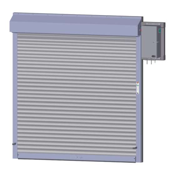
MODEL 523RX RESIDENTIAL EXTERIOR SECURITY SHUTTER,
500367.0001 NEW 10/08/2020
INSTALLATION INSTRUCTIONS
WITH SIDE MOUNT MOTOR ENCLOSURE
©Copyright 2020 Wayne Dalton, a division of Overhead Door Corporation
This installation manual provides
the trained door technician
information required to install
this door.
READ COMPLETE INSTRUCTIONS
BEFORE INSTALLING DOOR.
Some installation tasks listed in
this document are found in other
documents.
Please refer to the appropriate
document(s) as directed;
308577 Hilti Kwik Bolt Installation
found on Ribbon Connect
41510.00119 Installation
Instructions for Motor Enclosure
(Included)
This manual is intended ONLY
for professional use by a trained
door systems technician. All
others please refer to the end
user manual provided to you.
After installation is complete,
leave this manual with the
Homeowner. Maintenance
instructions on page 20.
1
Advertisement
Table of Contents

Subscribe to Our Youtube Channel
Related Manuals for Wayne-Dalton 523RX


Summary of Contents for Wayne-Dalton 523RX
- Page 1 INSTALLATION INSTRUCTIONS MODEL 523RX RESIDENTIAL EXTERIOR SECURITY SHUTTER, WITH SIDE MOUNT MOTOR ENCLOSURE This installation manual provides the trained door technician information required to install this door. READ COMPLETE INSTRUCTIONS BEFORE INSTALLING DOOR. Some installation tasks listed in this document are found in other documents.
-
Page 2: Table Of Contents
TABLE OF CONTENTS SECTION CONTENTS PAGES SAFETY INFORMATION KEY DRAWING DOOR INSTALLATION DATA SHEET PRE-INSTALLATION CHECK LIST INSTALLATION 7-14 MOTOR WIRING 15-17 FINAL INSTALLATION 18-19 MAINTENANCE INSTRUCTIONS WARRANTY 500367.0001 NEW 10/08/2020 ©Copyright 2020 Wayne Dalton, a division of Overhead Door Corporation... -
Page 3: Safety Information
SECTION 1 - SAFETY INFORMATION OVERVIEW OF POTENTIAL HAZARDS READ THIS SAFETY INFORMATION WARNING Upward Rolling Doors doors are large, heavy objects that move with the help of electric motors. Since moving objects and electric motors can cause injuries, your safety and the safety of others depends on you reading the information in this manual. If you have any questions or do NOT understand the information presented, call technical support at 1-800-764-1457. -
Page 4: Key Drawing
SECTION 2 - KEY DRAWING Please note that components and component locations are shown here for REFERENCE ONLY. FIG 2 Your unit installation and component locations may be different. 500367.0001 NEW 10/08/2020 ©Copyright 2020 Wayne Dalton, a division of Overhead Door Corporation... -
Page 5: Door Installation Data Sheet
SECTION 3 - DOOR INSTALLATION DATA SHEET A sample of the “DOOR INSTALLATION DATA” sheet is shown here. Locate the work order “Door Installation Data” sheet inside the door hardware box. You will need to refer to the “Door Installation Data” sheet. See FIG 2. Factory order number on door components must match with factory order number on the “Door Installation Data”... -
Page 6: Pre-Installation Check List
SECTION 4 - PRE-INSTALLATION CHECK LIST Verify that the door installation can be accomplished before proceeding: • Locate the work order “DOOR INSTALLATION DATA” sheet, see FIG 2, inside the door hardware box. • Does the wall opening shown in FIG 3 match the Opening Width and Height shown on the “Door Installation Data” sheet? •... -
Page 7: Installation
SECTION 5 - INSTALLATION STEP 1 STEP 1 INSTALL CURTAIN GUIDES TO JAMB • Mount curtain guides to the surface using supplied fasteners. See FIG 5A and 5B. • Check “G” Dimension as illustrated in FIG 4 on page 5. “G” Dimension must match your “DOOR INSTALLATION DATA” sheet. •... - Page 8 SECTION 5 - INSTALLATION STEP 2 STEP 2 INSTALL HEAD ASSEMBLY • Lift the head assembly using a fork lift or other appropriate lifting equipment and lower it onto the top of the guides, inserting the support bars into the guide as shown in FIG 6. •...
- Page 9 SECTION 5 - INSTALLATION STEP 2 STEP 2 INSTALL HEAD ASSEMBLY (Continued...) • Lift the fascia plate using a fork lift or other appropriate lifting equipment and lower it, attaching it to the back of the jamb, as shown in FIG 8. •...
- Page 10 SECTION 5 - INSTALLATION STEP 3 STEP 3 WIND SPRINGS WARNING Prior to winding or making adjustments to the springs, ensure you are winding in the proper direction as stated in the Installation Instructions. Otherwise the spring fittings may release from spring if not wound in the proper direction and could result in severe or fatal injury.
- Page 11 SECTION 5 - INSTALLATION STEP 4 STEP 4 ATTACH BOTTOM BAR STOPPER • With door in the closed position attach stopper using stud plate and nuts provided, as shown in FIG 12. FIG 12 500367.0001 NEW 10/08/2020 ©Copyright 2020 Wayne Dalton, a division of Overhead Door Corporation...
- Page 12 SECTION 5 - INSTALLATION STEP 5 STEP 5 ATTACH FRONT HOOD • Position the hood in place, as shown in FIG 13. • Align the hood and attach using the screws and wall fasteners provided. See FIG 13 and FIG 14. •...
- Page 13 SECTION 5 - INSTALLATION STEP 6 STEP 6 INSTALL OPERATOR • Lift the Motor Enclosure using appropriate lifting equipment and align the center of the bearing with the shaft. Insert the bearing onto the shaft all the way through the coupler attached to jackshaft operator in the box.
- Page 14 SECTION 5 - INSTALLATION STEP 6 STEP 6 INSTALL OPERATOR (Continued...) FIG 16 FIG 17 500367.0001 NEW 10/08/2020 ©Copyright 2020 Wayne Dalton, a division of Overhead Door Corporation...
-
Page 15: Motor Wiring
SECTION 6 - MOTOR WIRING IMPORTANT: REFER TO YOUR MOTOR ENCLOSURE INSTALLATION INSTRUCTIONS FOR WIRING AND PROGRAMMING THE OPENER. WARNING WARNING Incoming power must meet all NEC and local building codes, plus be properly sized for the motor. To avoid the risk of electrical shock, the motor must be properly grounded. - Page 16 SECTION 6 - MOTOR WIRING STEP 7 STEP 7 INSTALL INTERLOCK SWITCH (SKIP THIS STEP IF YOUR DOOR DID NOT COME WITH A INTERLOCK SWITCH) • Install interlock switch to the curtain guide, as shown in FIG 18. IMPORTANT: DO NOT REMOVE FACTORY INSTALLED INTERLOCK WIRE UNLESS INSTALLING AN INTERLOCK. THIS JUMPER IS REQUIRED FOR PROPER OPENER OPERATION.
- Page 17 SECTION 6 - MOTOR WIRING STEP 8 STEP 8 INSTALL PHOTO EYES • Install photo eyes onto the curtain guides, as shown in FIG 20. • Wire the photo eyes to the bottom of the Motor Enclosure using cable gland (water-tight) connector and to the STB connection, as shown in FIG 21. IMPORTANT: ONCE THE MOTOR ENCLOSURE IS COMPLETELY WIRED AND PROGRAMMED CORRECTLY, PROCEED WITH THE STEPS BELOW.
-
Page 18: Final Installation
SECTION 7 - FINAL INSTALLATION STEP 9 STEP 9 ATTACH GUIDE COVERS • Align guide covers on guides and snap into place. See FIG 22 and FIG 23. FIG 23 FIG 22 500367.0001 NEW 10/08/2020 ©Copyright 2020 Wayne Dalton, a division of Overhead Door Corporation... - Page 19 SECTION 7 - FINAL INSTALLATION STEP 10 STEP 10 PLACE WARNING LABEL • Place warning label on drive side guide at eye level. See FIG 24. WARNING MOVING door could result in death or serious injury. Do NOT close door until doorway is clear.
-
Page 20: Maintenance Instructions
MAINTENANCE INSTRUCTIONS OWNER’S RECOMMENDED PREVENTATIVE RECOMMENDED SCOPE OF WORK FOR PROFESSIONAL MAINTENANCE SECURITY SHUTTER PREVENTIVE MAINTENANCE PROGRAM To keep shutter in good working condition, these are some things we recommend doing: It is recommended that you arrange for a Wayne Dalton dealer’s professional installer/technician to perform the following as precautionary measures to keep •... -
Page 21: Warranty
500367.0001 NEW 10/08/2020 ©Copyright 2020 Wayne Dalton, a division of Overhead Door Corporation...
Need help?
Do you have a question about the 523RX and is the answer not in the manual?
Questions and answers