
Related Manuals for Megger Fault Sniffer 2


Summary of Contents for Megger Fault Sniffer 2
- Page 1 Fault Sniffer 2 Cable fault detection device OPERATING MANUAL Issue: F (01/2023) - EN Article number: 87150...
-
Page 3: Consultation With Megger
Megger All rights reserved. No part of this handbook may be copied by photographic or other means unless Megger have before- hand declared their consent in writing. The content of this handbook is subject to change without notice. Megger cannot be made liable for technical or printing errors or shortcomings of this handbook. -
Page 4: Terms Of Warranty
Megger accept responsibility for a claim under warranty brought forward by a customer for a product sold by Megger under the terms stated below. Megger warrant that at the time of delivery Megger products are free from man- ufacturing or material defects which might considerably reduce their value or us- ability. -
Page 5: Table Of Contents
Contents ....................5 1. Safety instructions ................7 1.1 Safety precautions ..................7 1.2 Identification of safety instructions ............... 7 1.3 Working with Megger products ..............7 1.4 Operating personnel ..................8 1.5 Repair and maintenance ................8 1.6 Unpacking ....................8 2. - Page 6 8.6 Performing tests ..................24 9. Calibration/adjustment ..............25 9.1 Test gases that may be used ..............25 9.2 Performing the calibration................26 9.3 Performing the adjustment ................ 27 10. Settings ................... 28 10.1 Opening and changing device settings ............ 28 10.2 Entering the password ................
-
Page 7: Safety Instructions
Safety precautions This manual contains basic information about commissioning and operating the Fault Sniffer 2. Therefore, it must be ensured that this manual is accessible to authorised and trained operating personnel at all times. The operating personnel must read the manual carefully. In no case shall the manufacturer be liable for any damage to persons or materials caused by failure to observe the safety in- structions contained in this manual. -
Page 8: Operating Personnel
(including safety goggles, protective gloves and safety footwear). Repair and maintenance Maintenance and repair work may only be carried out by Megger or an authorised partner. It is recommended to have the device and accessories checked once a year in a Megger service station. -
Page 9: Areas Of Application/Intended Use
How should the device be stored in case of prolonged non-use? If the Fault Sniffer 2 is not used for an extended period of time, the battery should be stored at between -20°C and +50°C for 30 days and at between -20°C and +30°C for one year. -
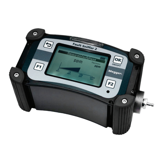
Page 10: Device Illustration/Controls
Device illustration/controls Description Display Optical alarm OK/ENTER and ON/OFF Gas inlet with connection nipple for probes Installed behind: Filters, integrated pump and sensors Tenax nipple for attaching a carrying strap (on both sides) Acoustic alarm Function keys F1 and F2 Charging socket (not shown here) BACK/ESC (Escape) key Charging socket... -
Page 11: Display
Display The display is a graphics-capable LCD display and allows measured values and text information to be displayed clearly. Clean the display regularly. Description of the display Display symbols in the top line of the display for active and inactive functions as well as the permanent display of the charge level Battery charge level Measurement data is saved... -
Page 12: Acoustic Alarm
Acoustic alarm The acoustic alarm is the buzzer below the F2 function key. This sounds for im- portant events or error messages. Optical alarm An optical alarm is indicated by several bright alarm LEDs above the display. The LEDs flash at the same frequency as the acoustic signal sounds. Bluetooth (integrated) The integrated Bluetooth module is used for standard data transfer and for up- dating the device firmware. -
Page 13: Nameplate
Nameplate The nameplate with the device name, article number (PN) and serial number (SN) is on the back of the device. Storage, transport, packaging After unpacking, during transport and before and after storage, check the device for visible damage. If there is any damage, please contact your sales partner. Power supply (charging) To be able to use the device at any time, check the charge level of the Li-ion battery. -
Page 14: Operation/Handling
Operation/handling Switching the device on and off Switching on the device 1. Press ON/OFF (OK/ENTER) for at least 2 sec- onds. 2. Wait for the system and pump test. 3. Confirm the service date with CONTINUE (if displayed). Result: The device displays the main menu. Switching off the device The device can only be switched off from the main menu. -
Page 15: Selecting The 'Info' Menu And Checking The Values
Selecting the 'Info' menu and checking the values The 'Info' menu displays the serial number (SN), software version, free memory, date, time, and bat- tery charge level. Confirming the service date The service date is displayed when the device is started to inform the user. -
Page 16: Changing The Filter
Changing the filter Filters are designed to protect the measuring device from serious dam- age. Moist or dirty filters reduce the flow rate and extend the response time of the measuring device. The proper function of the device can only be guaranteed when the filters are dry and clean. - Page 17 Filter assembly: ① No. Description ② Dust filter ③ Hydrophobic membrane 1 (do not touch!) ④ Filter housing Hydrophobic membrane 2 (do not touch!) Replacing the dust filter The dust filter should be changed much more frequently than the entire filter housing (depending on the conditions of use, in a ratio of 10:1).
-
Page 18: Replacing Filters In The Water Blocker
Replacing the complete filter housing The hydrophobic filter/hydrophobic membrane must not be touched with bare fingers, as this will damage it! Preliminary work • Clean the device and screw cap (so that it is free from dust and moisture) • Make sure that tweezers are at hand Replacing 1. -
Page 19: Cable Fault Detection
Cable fault detection With cable fault detection, you can detect the smallest gas concentrations of burnt insulation material above or in the ground. Probes are connected to the device for detection. The gases are directed to the sensors via the integrated pump in the device. -
Page 20: Examples For The Use Of The Probes
In addition to the two probes supplied, gases can also be directed to the sen- sors via the optional VSS 15 vacuum probe system. Detailed information on the use of the vacuum probe system can be found in the relevant operating instructions. Examples for the use of the probes The figures illustrate the differences in measurement results due to the use of the probes under different conditions. - Page 21 All the illustrations show an example of the gas quantity and gas distribution, a display and a trend arrow of the measured ppm value. With the bell probe ①, you can measure gases oc- curring directly on the ground. The smallest amounts of gas on the ground are also an indication that high concentrations can be found below the surface.
-
Page 22: Display Of Gas Concentrations
Display of gas concentrations Two different displays of the gas concentration are integrated in the device. • The gas concentration of burnt insulation material • The gas concentration of natural gas or a gas similar to natural gas If the device displays the gas alarm, you should pass this information on to the competent authorities known to you. -
Page 23: Resetting The Maximum Value
Resetting the maximum value Method (which display will Procedure reset?) Manual If no more gas is measured, you can reset the maximum value with F1 after a short time. (Number and line) Alarms In certain situations, an alarm is sounded via the device's signal generator. The alarms with the associated message on the display are: When is the alarm triggered? Display... -
Page 24: Performing Tests
Performing tests For longer periods of work, wear the Fault Sniffer 2 together with the waist belt to protect your back. This is the only way to distribute the weight of the device over a large area in a way that is gentle on your back. -
Page 25: Calibration/Adjustment
If the calibration/adjustment fails after several attempts, please contact the manufacturer. Sensors may have been damaged due to prolonged contact with very high gas concentrations or other influences. Test gases that may be used Only use the test gas recommended and distributed by Megger. -
Page 26: Performing The Calibration
Performing the calibration You can perform the calibration in a menu-guided way. Observe the operating instructions shown on the display. You can press BACK/ESC to cancel the calibration at any time. Requirements • Test gas is available, but is not yet connected to the device. •... -
Page 27: Performing The Adjustment
Performing the adjustment You can perform the adjustment in a menu-guided way. You must perform the calibration before and af- ter the adjustment. This is because you can only per- form the adjustment by means of a previous calibra- tion. And you use the subsequent calibration to check the newly adjusted sensors. -
Page 28: Settings
Settings 10.1 Opening and changing device settings Requirement: Device password In the settings, you can select different menu items depending on the authorisation level. The illustration on the right shows an example and an excerpt of menu items in the settings. The default password is 1000. -
Page 29: Changing The Language Of The Device
10.3.1 Changing the language of the device Select the 'General' menu item. In addition to the standard languages German and English, you can select other available languages. If the language you are looking for is not available, please contact your sales representative. 10.3.2 Setting the time for the auto power down of the device Select the 'General' menu item. -
Page 30: Cable Fault Detection
10.5 Cable fault detection 10.5.1 Cable fault detection (overview) Display Range Show MI Yes/No (Show cable fault detection menu item) Save Yes/No 10.5.2 Showing and hiding the menu item in the main menu Select the 'Cable fault detection' menu item and 'Show MI'. You can specify whether the menu item (MI) should be displayed in the main menu or not. -
Page 31: Technical Data
Technical data The Fault Sniffer 2 is specified by the following technical parameters: Name : Fault Sniffer 2 cable fault detection device : Approximately 192 x 100 x 87 mm (without gas inlet Dimensions screw) Weight : Approximately 1150 g... -
Page 32: Optional Accessories / Spare Parts
Optional accessories / spare parts The following spare parts and accessories can be purchased from the relevant Megger sales representative: Description Item number VSS 15 vacuum probe system 1012956 Replacement set - EFI1 filter (3 pieces), dust filter for gas inlet... -
Page 33: Error Messages/Troubleshooting
Error messages/troubleshooting The following are error messages and error codes with short descriptions for trou- bleshooting. This information will help you to perform the appropriate action rec- ommended by the device manufacturer when messages appear. Message or error Possible cause or mean- Solution approach or contact person CONFIG Configuration is not pre-... - Page 34 Message or error Possible cause or mean- Solution approach or contact person Service appointment Device must be sent in for service. expired! Sensor error de- Device must be sent in for service. tected! Service re- quired! followed by… Error 01 08...
Need help?
Do you have a question about the Fault Sniffer 2 and is the answer not in the manual?
Questions and answers