
Subscribe to Our Youtube Channel
Related Manuals for Megger CFL510F


Summary of Contents for Megger CFL510F
- Page 1 CABLE FAULT LOCATOR MEGGER ® CFL510F (TDR1000/2) User Guide MEGGER ® GlobalTestSupply www. .com Find Quality Products Online at: sales@GlobalTestSupply.com...
-
Page 2: Safety Warnings
SAFETY WARNINGS Although this tester does not generate any hazardous voltages, circuits to which it can be connected could be dangerous due to electric shock hazard or due to arcing (initiated by short circuit). While every effort has been made by the manufacturer to reduce the hazard, the user must assume responsibility for ensuring his, or her own safety. -
Page 3: Table Of Contents
Contents Safety Warnings Introduction General description Battery replacement User Controls and Display Layout and functions Operation General Testing procedure Symbols used on the instrument are: Line Feed Connection to cable under test Measuring distance to fault Caution:Referto accompanying notes. Menu TX Null Velocity Factor Equipment protected throughout by... -
Page 4: Introduction
Reflections are caused by changes in the cables The CFL510F can be used on any cable consisting of GlobalTestSupply www. .com Find Quality Products Online at:... - Page 5 The CFL510F has internal matching networks to allow testing of 25, 50, 75 and 100 cables. (These typically correspond to power, coaxial data and data/telecoms cable).
- Page 6 Battery fitting and replacement When the low battery symbol appears in the display window the cells are nearly exhausted and should be replaced as soon as possible. Use alkaline cells IEC LR6 (AA) 1.5V or 1.2V rechargeable cells only. To install or replace the cells, switch the instrument off.
-
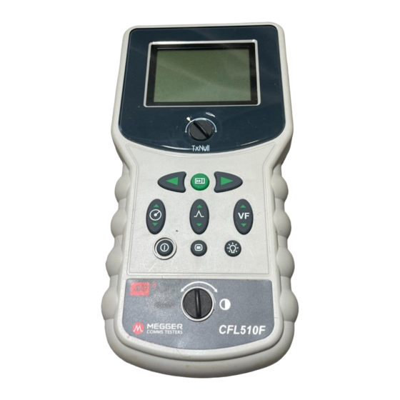
Page 7: User Controls And Display
User controls and display The controls of the TDR have been arranged such that Instrument Display: The display shows the user the the instrument is easy to learn and use. The instrument current settings of the instrument and the reflected controls consist of the following energy trace from the cable connected. - Page 8 User controls and display Find key: Automatically moves the cursor to Menu: Allows the user to change the units of the first potential fault (change of impedance). measurement for Distance, Velocity Factor, Impedance and Test Rate. Refer to menu section later in this text. Power: Pressing this button will turn the instrument on or off depending on its current...
-
Page 9: Operation
Ensure that the whole length of the cable can be seen sockets of the instrument. on the display, and that the range selected is correct. Switch on the instrument. The CFL510F will display Find key the start screen for a couple of seconds, followed by... - Page 10 Operation In the event of no reflections being visible, increase 0.67R gain until any reflection can be easily identified. (If no reflections can be seen, try shorting or earthing the far end of the cable to ensure that you are “seeing”...
-
Page 11: Menu
The Menu key allows the user to change the units of keys. measurement Distance, Velocity factor, Impedance and Test Rate. By pressing the Menu key the CFL510F will display: Distance Unit VF Format RATIO Impedance 75Ω Test rate Available options... -
Page 12: Tx Null
Operation TX Null Velocity Factor Without the “TX Null” control, the transmitted pulse would The velocity factor is used by the instrument to be visible at the beginning of the trace, swamping any convert the measured time for a pulse to be reflected, reflections within the pulse length (the dead zone). -
Page 13: Pulse Widths
Operation Pulse Widths Test the cable from both ends As the RANGE and IMPEDANCE matching of the When fault finding a cable it is good practice to take TDR are adjusted so the duration of the transmitted measurements from both ends. Particularly in the case pulse changes. - Page 14 Operation Except where otherwise stated, this specification Output pulse: 5 volts peak to peak into open applies at an ambient temperature of 20C. circuit. Pulse widths determined by range and cable impedance: General 25Ω 50Ω 75Ω 100Ω Ranges: 10m, 30m, 100m, 300m, 1000m, 3000m (30ft, 100ft, 300ft, 1000ft, 3000ft, 10000ft) 20ns 20ns...
-
Page 15: Specifications
Specifications Backlight: Stays on for 1 minute when activated. Mechanical Batteries: Six LR6 (AA) type batteries, The instrument is designed for use indoors or Manganese-alkali or outdoors and is rated to IP54. nickel-cadmium or Case Dimensions: 230 mm long (9 inches) nickel-metal-hydride cells 115 mm wide (4.5 inches) Nominal voltage:... - Page 16 Ordering information TDR 1000/2 Included Accessories Optional Accessories Test & Carry case with strap 6420-125 Fused prod and clip set 6111-218 Miniature Clip Test Lead Set 6231-652 User Guide 6172-659 For use on energised systems rated up to 300V CATIII use the fused prod and clip set AVO Part Number 6111-218, must be used.
- Page 17 Fax: +1 (214) 337-3038 This instrument is manufactured in the United Kingdom. The company reserves the right to change the specification or design without prior notice. MEGGER is the registered Trade Mark of AVO INTERNATIONAL LIMITED. © Copyright , AVO INTERNATIONAL LIMITED.
Need help?
Do you have a question about the CFL510F and is the answer not in the manual?
Questions and answers