ARAG BRAVO 300S Series Directions For Installation, Use And Maintenance
Hide thumbs
Also See for BRAVO 300S Series:
- Quick reference manual (2 pages) ,
- Installation manual (20 pages) ,
- Installation, use and maintenance manual (52 pages)

Related Manuals for ARAG BRAVO 300S Series


Summary of Contents for ARAG BRAVO 300S Series
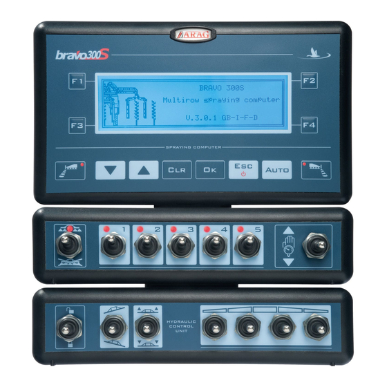
- Page 1 300S BRAVO SERIES COMPUTER DIRECT CONNECTION 46730X01 Software rel. 3.2.x INSTALLATION, USE AND MAINTENANCE...
- Page 2 This manual is an integral part of the equipment to which it refers and must accompany the equipment in case of sale or change of ownership. Keep it for future reference; ARAG reserves the right to modify the specifications and instructions...
-
Page 3: Table Of Contents
CONTENTS • Manual foreword and use ..............................5 • Manual use modes ................................5 • Limitations ..................................5 • Responsibility ..................................5 1 Risks and protections before assembly .......................... 6 2 Bravo DSB ..................................6 3 Intended use ..................................6 4 Precautions .................................. - Page 4 CONTENTS 12 Job functions ................................... 31 12.1 F1 - Job selection (Page 1) ............................32 12.2 F2 - Current job data (Page 1)..........................32 12.3 F2 - Logger ON? (Page 2) ............................33 12.4 F3 - Zero transducer setup (Page 1) ........................33 12.5 F4 - Tank (Page 1) ..............................33 12.6 F4 - User setting (Page 2) ............................33 13 Use ....................................
-
Page 5: Manual Foreword And Use
• RESPONSIBILITY The installer must carry out workmanlike installations and ensure to the end user the perfect operation of the whole system both with ARAG components only and other brands' components. ARAG always recommends using its components to install control systems. -
Page 6: Risks And Protections Before Assembly
BRAVO DSB ARAG has designed and manufactured a diagnostics system for Bravo series computers and the systems they may be connected to. BRAVO DSB (code 467003) provides reliable diagnostics of computer, control unit or the whole system to troubleshoot any potential problems experienced with the BRAVO DSB system. -
Page 7: Position On Farming Machine
INSTALLATION POSITION ON FARMING MACHINE System recommended composition DIRECT CONNECTION ASSEMBLY DIAGRAM FOR CROP SPRAYERS WITH MEMBRANE PUMP Legend: Bravo 300S Battery Filling pump Flowmeter Main valve Pressure sensor Control valve Foam marker Speed sensor Filling flowmeter / Pump Protector / RPM sensor Level sensor 1÷5 Section valves... -
Page 8: Monitor Position
Monitor position The Bravo 300S series computer must be placed in the control cabin of the farming machine. Observe the following precautions: - DO NOT install the monitor in areas where it would be subjected to excessive vibrations or shocks, to prevent any damage or accidental use of the control keys;... -
Page 9: Computer Connection To The Farming Machine
INSTALLATION COMPUTER CONNECTION TO THE FARMING MACHINE General precautions for a correct harness position • Securing the cables: - secure the harness so that it does not interfere with moving parts; - route the harnesses so that they can not be damaged or broken by machine movements or twisting. •... -
Page 10: Connecting The Cable To The Control Unit And Services
• Take care not to break, pull, tear or cut the cables. • Use of unsuitable cables not provided by ARAG automatically voids the warranty. • ARAG is not liable for damages to the equipment, persons, animals or things caused by failure to observe the above instruc- tions. -
Page 11: Connection Of Sensors And Other Available Functions
• filling flowmeter; • RPM sensor; • foam marker. All ARAG sensors use the same type of connector. Connect the sensor connector to the relevant harness; make sure it is correctly fitted and push it until locking it. Fig. 9a... -
Page 12: Sd Memory Card
INSTALLATION SD memory card The SD memory card is used to exchange data with the Bravo 300S computer. (Fig. 10b). Before using it, make sure the card is not protected ONLY use the SD card supplied with the package. Fig. 10a Fig. -
Page 13: Setup
PROGRAMMING SETUP Tests and checks before programming Before computer programming, ensure: • that all components are correctly installed (control unit and sensors); • the connection to the power source; • the component connection (main control unit and sensors). Failure to correctly connect system components or to use specified components might damage the device or its components. Computer switching ON/OFF •... -
Page 14: Use Of Keys For Programming
PROGRAMMING Use of keys for programming Advanced Setup > Language English 1 Use cursor to select the menu you want to access: Unit of measurement Metric move it using the “arrow” keys until selecting the option you are looking for (Fig. 15). Section valves number 2 Confirm the selection with >... -
Page 15: Advanced Setup
ADVANCED SETUP ADVANCED SETUP The computer can be set-up with all data required to ensure a correct distribution of the treatment product. This operation must be done once only, when installing the computer. ACCESS TO ADVANCED SETUP MENU Advanced Setup Advanced setup (with computer off) Language English... -
Page 16: Language
ADVANCED SETUP 10.1 Language Set the language of Bravo 300S, among those available. > Italiano, English, Español, Português, Français, Deutsch, Polski, Русский, Cesky, Polski, , Hrvatski, Magyar, Lietuviu. Fig. 21 The list of the available languages changes according to the language package supplied with the computer: if the display does not feature the language you need, update the firmware. -
Page 17: Boom Setup
ADVANCED SETUP 10.4 Boom setup Setting the width of individual boom sections and total number of nozzles. Select one Boom setup (20.00 m) item Nozzle number : 40 Section 1 : 4.00 m Section 2 : 4.00 m Section 3 : 4.00 m Section 4 : 4.00 m... -
Page 18: Valves
ADVANCED SETUP 10.5 Valves Set the type of valves installed on the system and the relevant data. Select one > Boom section item : indicate the type of installed valves. 2 ways : valve without calibrated backflows 3 ways : valve with calibrated backflows >... -
Page 19: Pressure Sensor
(Fig. 30). Fig. 30 The table below indicates the values that are automatically set selecting the sensor code: ARAG PRESSURE SENSOR Max. pressure TYPE ARAG 466112.200 50.0 The default values can be ARAG 466112.500... -
Page 20: Rev Counter (Rpm Sensor)
ADVANCED SETUP 10.11 Rev counter (RPM Sensor) Select Set the data of the RPM sensor (if installed in the system): one item > Constant : indicate the constant of the installed RPM sensor. If the RPM sensor is not installed, press : in this case the display will show the Disabled Minimum speed alarm... -
Page 21: Configuration Check After Advanced Setup End
ADVANCED SETUP 10.14 Configuration check after Advanced setup end Advanced setup This screen is displayed only in case of errors upon end: Select one error In case of more error messages, select the message and press Advanced setup Bravo 300S automatically passes to the and directly positions on the value to be modified. -
Page 22: User Setting
USER SETTING USER SETTING ACCESS TO USER SETTING User setting User setting (from computer ON) Speed • Keep pressed until the menu is displayed. Jobs setup Nozzles setup For a correct use of the keys during setting, refer to Par. 9.3. Working limits Flowrate correct.factor User preferences... -
Page 23: Speed
USER SETTING 11.1 Speed Usually the computer calculates the information concerning the speed thanks to pulses received by the sensor installed on the wheel. If a GPS receiver is directly connected to the Bravo 300S, this menu allows selecting the receiver as alternative source to the wheel sensor, and so to receive in real time the speed data provided by the GPS. -
Page 24: Jobs Setup
USER SETTING 11.2 Jobs setup In this menu it is possible to set 19 different types of treatments. Select one job Active job Jobs setup ISO01 Orange ISO015 Green ISO02 Yellow Jobs setup 03 Disabled Target rate Disabled Nozzle Yellow ISO02 Disabled Disabled... -
Page 25: Nozzles Setup
USER SETTING 11.3 Nozzles setup This menu allows setting 12 types of ISO nozzles and 5 customized (by the user) nozzles. Select one nozzle Type A Flowrate 1.00 l/min. Pressure 5.0 bar Minimum pressure alarm Disabled Maximum pressure alarm Disabled Legend: A Nozzle number Fig. -
Page 26: Flowrate Correct. Factor
USER SETTING 11.5 Flowrate correct. factor When using a paddle flowmeter and the sprayed fluid has a different density than the water one, the computer could display wrong measurements; to correct them change the sprayed fluid factor: • if at the end of the spraying the tank still contains fluid, reduce the factor; •... -
Page 27: Date & Time
USER SETTING 11.7 Date & Time This menu allows setting the computer clock. > Modification locking code Allows locking the modification of date and time set on the computer to obtain real reports. • HOW TO USE THE LOCKING CODE - Enter the number to enable the locking;... -
Page 28: Test
USER SETTING 11.9 Test Test Speed simulation (S) Speed (F) Flow (M) Pressure Allows checking the correct operation of Bravo 300S. (T) Filling flowm. (X) Rev. counter Tests are READING-ONLY data. Battery voltage Display Keyboard & Switches GPS data Monitor software version V.1.33 Fig. - Page 29 USER SETTING > Keyboard and Switches Press all keys or switches one at a time: if the operation is correct, the display will show the name of the relevant control. Keyboard & Switches Keyboard Keyboard: H2O switches Foam marker LEFT DOWN Auto Foam marker RIGHT Fig.
-
Page 30: Load/Save Setup
USER SETTING 11.10 Load/save setup The 300S settings can be loaded or saved on SD card so as to reconfigure the device if necessary, solve problems or configure another Bravo 300S without repeating all operations manually. Once installation is completed, and you have checked machine correct operation, we recommend storing the whole configuration onto SD card. - Page 31 WORK FUNCTIONS When the list is active, pressing the key at the side will activate the relevant function. The display does not actually indicate the page number, it is shown here just for ease of reference. FUNCTION LIST DISPLAYING • PAGE 1 Fig.
-
Page 32: F1 - Job Selection
WORK FUNCTIONS Jobs setup Select the type of treatment to perform, among those preset in the menu (Par. 11.2). Select > one job Active job Job selection - Select the type of treatment and press Bravo 300S automatically quits the procedure and passes to the job screen. >01) 60 l/ha ISO01 Orange... -
Page 33: F2 - Logger On
WORK FUNCTIONS 12.3 F2 - Logger ON? (PAGE 2) Logger ON? Logger OFF? Enable/disable application data logging. Par. Fig. 72 User setting/ 11.8 Data logger: ...sec. 12.4 F3 - Zero transducer setup (PAGE 1) Activate the "zero" calibration procedure of pressure sensor. In case a pressure value is displayed despite the absence of pressure inside the circuit, it is necessary to perform zero setup of the sensor: - Press... -
Page 34: Use
13.1 Controls on computer Legend: 1 Function keys (Chap. 12 - Job functions) 2 Keys to select data or modify parameters 3 Foam marker control keys 4 Operating switches for control unit valves Fig. 76 13.2 Control, selection or modification keys ON/OFF Output Foam marker... -
Page 35: Treatment Preliminary Settings
13.5 Treatment preliminary settings Par. 11.1 Speed 11.2 Jobs setup 11.3 Nozzles setup TO BE CARRIED OUT 11.4 Working limits UPON FIRST USE OF 11.5 Flowrate correction factor After having carried out the indicated settings start the THE COMPUTER 11.6 User preferences treatment selecting between MANUAL (Par. -
Page 36: Section Valves Automatic Switch-Off (Through Skipper)
MAINTENANCE / DIAGNOSTICS / REPAIRS 13.7 Automatic closure of the main valve (through SKIPPER) BRAVO 300S can automatically switch off main valve through SKIPPER: the navigator can autonomously manage valve opening and closing, thus preventing the overlapping of already-sprayed areas. To use the automatic closure, connect SKIPPER to BRAVO 300S and carry out the AUTOMATIC operation procedure (Par. -
Page 37: Troubleshooting
MAINTENANCE / DIAGNOSTICS / REPAIRS 14.2 Troubleshooting FAULT CAUSE REMEDY • Check power supply connection (Par. 7.2). No power supply The display does not switch on Computer is OFF • Press the ON key. Valve controls take no effect Valves not connected •... -
Page 38: Technical Data
TECHNICAL DATA TECHNICAL DATA • Advanced menu Data Description Min. Max. Notes Lingue impostabili: Italiano, English, Español, Português, Language Display language Français, Deutsch, Polski, Русский, Cesky, Polski, Hrvatski, Magyar, Lietuviu. Unit of measurement Display unit of measurement Values that can be set: Metric, US Number of section control valves in Section valves number Values that can be set: 1 ÷... - Page 39 TECHNICAL DATA • User setting Data Description Min. Max. Notes Source Values that can be set: Wheel sensor, GPS. Selected wheel type Possibility to save up to three types of wheel Wheels setting Groups sub-menus: Constant calculation, Wheel constant Constant calculation Value that can be set: Manual, Automatic Speed Metric: cm/pls...
-
Page 40: Computer Technical Data
TECHNICAL DATA 15.1 Computer technical data Description Bravo 300S Display White backlit 240 x 64 graphic LCD Power supply 11 ÷ 14 Vdc Consumption (valves excluded) 450 mA 0 °C ÷ 60 °C Working temperature +32 °F ÷ +140 °F Digital inputs for open collector sensors: max 2000 imp/s Analog input... - Page 41 Notes...
-
Page 42: Guarantee Terms
GUARANTEE TERMS 1. ARAG s.r.l. guarantees this apparatus for a period of 360 days (1 year) from the date of sale to the client user (date of the goods delivery note). The components of the apparatus, that in the unappealable opinion of ARAG are faulty due to an original defect in the material or production process, will be repaired or replaced free of charge at the nearest Assistance Centre operating at the moment the request for intervention is made. - Page 43 Only use genuine ARAG accessories or spare parts to make sure manufacturer guaranteed safety conditions are maintained in time. Always refer to the internet address www.aragnet.com 42048 RUBIERA (Reggio Emilia) - ITALY Via Palladio, 5/A Tel. +39 0522 622011 Fax +39 0522 628944 www.aragnet.com...
Need help?
Do you have a question about the BRAVO 300S Series and is the answer not in the manual?
Questions and answers