ARAG Bravo 300S Series Installation, Use And Maintenance Manual
Computer multi-row sprayer
Hide thumbs
Also See for Bravo 300S Series:
- Quick reference manual (2 pages) ,
- Installation manual (20 pages) ,
- Directions for installation, use and maintenance (43 pages)

Related Manuals for ARAG Bravo 300S Series


Summary of Contents for ARAG Bravo 300S Series
- Page 1 300S Bravo SerieS computer muLti-roW SpraYer • DIRECT CONNECTION: 46731XXX • RCU: 46733XXX Software rel. 3.1x INSTALLATION, uSe ANd mAINTeNANce...
- Page 2 This manual is an integral part of the equipment to which it refers and must accompany the equipment in case of sale or change of ownership. Keep it for any future reference; ARAG reserves the right to modify product specifications and...
-
Page 3: Table Of Contents
CONTENTS • Manual foreword and use ..............................5 • Manual use modes ................................5 • Limitations ..................................5 • Responsibility ..................................5 1 Risks and protections before assembly .......................... 6 2 Bravo DSB ..................................6 3 Intended use ..................................6 4 Precautions ..................................6 5 Package content ................................6 6 Position on farming machine ............................7 System recommended composition ........................... - Page 4 CONTENTS 11 User setting ..................................28 11.1 Speed ..................................29 11.1.1 Source - Wheel sensor ............................. 29 11.1.2 Source - GPS ................................29 11.2 Jobs setup ................................30 11.3 Nozzles setup ................................31 11.4 Booms setup ................................31 11.5 Working limits ................................32 11.6 Flowrate correct.
-
Page 5: Manual Foreword And Use
• responsibiLity The installer must carry out workmanlike installations and ensure to the end user the perfect operation of the whole system both with ARAG components only and other brands' components. ARAG always recommends using its components to install control systems. -
Page 6: Risks And Protections Before Assembly
ARAG has designed and manufactured a diagnostics system for Bravo series computers and the systems they may be connected to. BRAVO DSB (code 467003) provides reliable diagnostics of computer, control unit or the whole system to troubleshoot any potential problems experienced with the BRAVO DSB system. -
Page 7: Position On Farming Machine
INSTALLATION position on farming machine System recommended composition direct connection assembLy diagram for muLti-row sprayer with diaphragm pump - system with main vaLve Legend: Monitor Battery Filling pump Flowmeter Main valve Pressure sensor Control valve Foam marker Speed sensor Filling flowmeter / Pump Protector / RPM sensor Level sensor 1÷5 Section valves Fig. 3 direct connection assembLy diagram for muLti-row sprayer with diaphragm pump - system with drain vaLve Legend: Monitor Battery Filling pump Flowmeter... - Page 8 INSTALLATION direct connection assembLy diagram for muLti-row sprayer with centrifugaL pump Legend: Monitor Battery Filling pump Flowmeter Pressure sensor Control valve Foam marker Speed sensor Filling flowmeter / RPM sensor Level sensor 1÷5 Section valves Fig. 5 assembLy diagram for muLti-row sprayer with diaphragm pump - system with main vaLve Legend: Monitor Battery Filling pump Hydraulic unit Flowmeter Main valve Level sensor Pressure sensor Control valve...
- Page 9 INSTALLATION assembLy diagram for muLti-row sprayer with diaphragm pump - system with drain vaLve Legend: Monitor Battery Filling pump Hydraulic unit Flowmeter Drain valve Level sensor Pressure sensor Control valve Foam marker Speed sensor Filling flowmeter / Pump Protector RPM sensor 1÷5 Section valves Fig. 7 assembLy diagram for muLti-row sprayer with centrifugaL pump Legend: Monitor Battery Filling pump Hydraulic unit Flowmeter Level sensor...
-
Page 10: Monitor And Control Unit Positioning
INSTALLATION Monitor and control unit positioning • BRAVO 300S series computer must be placed in the control cabin of the farming machine. Observe the following precautions: - Do NOT install the monitor in areas where it would be subjected to excessive vibrations or shocks, to prevent any damage or accidental use of the control keys; - Install the device in a visible position within easy reach by hand; bear in mind that the computer should not obstruct the operator’s freedom of movement or block his view. • Control unit (RCU): secure the control unit on the back of the machine, close to the control unit and the hydraulic unit. -
Page 11: Bracket Fixing
The control unit must be fixed with the special brackets supplied and fitted to the unit, positioning it as shown in the manual provided with the assembly. MAKE SURE TO FOLLOW ALL THE SAFETY INSTRUCTIONS GIVEN IN THE CONTROL UNIT’S MANUAL. 6.6 Hydraulic unit positioning The hydraulic unit shall be secured to the machine, making sure it is well protected against the elements and the fluid sprayed by the machine. ARAG IS NOT LIABLE FOR ANY DAMAGE RESULTING FROM THE INSTALLATION BY UNSKILLED PERSONNEL. ANY SYSTEM DAMAGE CAUSED BY A WRONG INSTALLATION AND/OR CONNECTION AUTOMATICALLY VOIDS THE WARRANTY. WARNING! DO NOT CONNECT HYDRAULIC UNITS OTHER THAN THE SPECIFIED ONES (SEE ARAG GENERAL CATALOGUE). ARAG IS NOT LIABLE FOR ANY DAMAGE TO THE PRODUCT, MALFUNCTION ERRORS AND ANY KIND OF RISK IF THE MODULE IS CONNECTED TO NON ORIGINAL UNITS OR UNITS NOT SUPPLIED BY ARAG. -
Page 12: Computer Connection To The Farming Machine
INSTALLATION computer connection to the farming machine General precautions for a correct harness position • Securing the cables: - secure the harness so that it does not interfere with moving parts; - route the harnesses so that they can not be damaged or broken by machine movements or twisting. • Routing the cables to protect against water infiltrations: - the cable branches must ALWAYS be face downwards (see figures below). direct connection Fig. -
Page 13: Power Supply Connection
INSTALLATION Power supply connection The package includes the power connector (Fig. 1 and Fig. 2 on page 6) to be connected to the farming machine battery; Fig. 20 shows the drilling template of the power connector. Connect the power connector to the battery wires using two 6-mm faston connectors, as indicated in Fig. 18 and Fig. 19. Use the cable provided with the package (Fig. -
Page 14: Harness Connection To The Control Unit, The Hydraulic Unit And The Available Functions
INSTALLATION harness connection to the controL unit, the hydrauLic unit and the avaiLabLe func- tions • Use only the cables provided with the ARAG computers. • Take care not to break, pull, tear or cut the cables. • Use of unsuitable cables not provided by ARAG automatically voids the warranty. • ARAG is not liable for damages to the equipment, persons, animals or things caused by failure to observe the above instructions. Multicore connector connection (FOR VERSIONS WITH DIRECT CONNECTION ONLY) Connect the multicore connector to the monitor (connection “1” on page 10); check it is correctly connected, and turn the ring nut clockwise until connector blocking. Remote control unit (RCU) connection , Fig. 22). • Open connector slide ( •... -
Page 15: Hydraulic Valves Connection
INSTALLATION Fig. 24 Fix the connectors to the relevant valves according to the initials indicated in your assembly general diagram (Par. 6.1 System recommended composition). • Remove the protection cap (1, Fig. 24) from the electric valve. • Place the seal (2) onto the connector (3), and push the connector fully on (4): be careful not to bend the contacts upon insertion on the valve. •... -
Page 16: Connection Of Sensors And Other Available Functions
• filling flowmeter; • RPM sensor; • foam marker. All ARAG sensors use the same type of connector. Connect the sensor connector to the relevant harness; make sure it is correctly fitted and push it until locking it. Fig. 25... -
Page 17: Sd Memory Card
INSTALLATION SD memory card The SD memory card is used to exchange data with the BRAVO 300S computer. Before using it make sure the card is not protected (Fig. 27). ONLY use the SD card supplied with the package. Fig. 27 Fig. 28 Before inserting or removing the SD memory card ALWAYS switch off the computer. • Insertion: Insert the memory card making sure to orient it correctly: the card cut edge A must be face downward; push the card until it engages into place and close the slot with the cover. -
Page 18: Setup
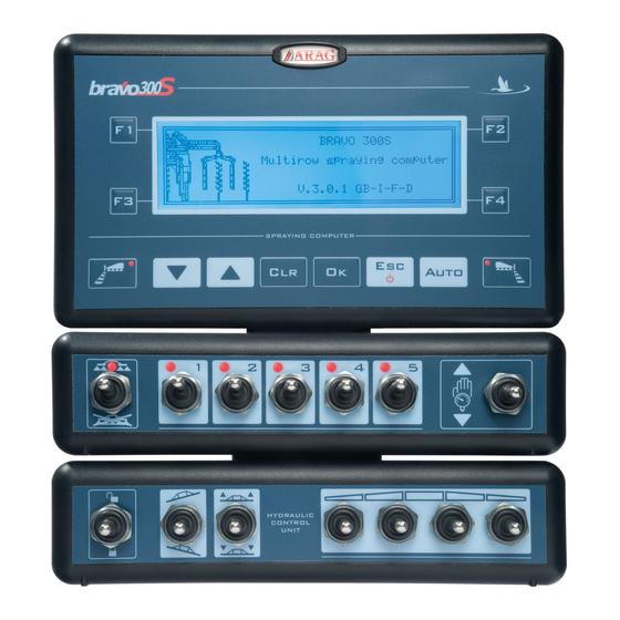
PROGRAMMING setup Tests and checks before programming Before computer programming, ensure: • that all components are correctly installed (control unit and sensors); • the connection to the power source; • the component connection (main control unit and sensors). Failure to correctly connect system components or to use specified components might damage the device or its components. Computer switching On/Off • Ordinary switching on Software version Job screen Fig. 30 Keep key pressed until switching on the display: after the software version, Bravo 300S displays the job screen (Fig. 30). NOTE: The starting screen changes according to the model you have purchased. • Switching on to activate the advanced setup Fig. 31 Contemporaneously press the key sequence until switching on the Bravo. -
Page 19: Use Of Keys For Programming
PROGRAMMING Use of keys for programming > Use cursor to select the menu you want to access: move it using the “arrow” keys until selecting the option you are looking for (Fig. 33). Confirm the selection with Fig. 33 data seLection When it is about a simple selection of data, BRAVO 300S displays the active value (2a, Fig. -
Page 20: Advanced Setup
ADVANCED SETUP advanced setup The computer can be set-up with all data required to ensure a correct distribution of the treatment product. This operation must be done once only, when installing the computer. access to advanced setup menu Advanced setup (with computer off) • Contemporaneously press the key sequence until switching on the Bravo. • Release the key by keeping the arrow keys pressed until the menu is displayed. -
Page 21: Language
ADVANCED SETUP 10.1 Language Set the language of Bravo 300S, among those available > Italian English Español Português Français, Deutsch Cesky Polski Fig. 39 Русский Hrvatski The list of the available languages changes according to the language package supplied with the computer: if the display does not feature the language you need, update the firmware. The firmware with ALL available language packages can be found on the SD provided with Bravo 300S; the update procedure is described in the ADDIN code D30053 that you find on the CD-ROM provided with this manual. 10.2 Unit of measurement Set the units of measurement used for Bravo 300S. >... -
Page 22: Valves
ADVANCED SETUP Application systems: 1.50 Rows • section 1 sprays on one complete row and on one side of the next row (Fig. 47 - set value Fig. 47 1.00 Rows • section 1 sprays on one complete row (Fig. 48 - set value 0.50 Rows •... -
Page 23: Flowmeter
Maximum pressure When the option is activated, the item is no longer displayed (Fig. 45). Fig. 45 The table below indicates the values that are automatically set selecting the sensor code: arag pressure sensor Max. pressure TYPE ARAG 466113.200 20.0 The default values can be ARAG 466113.500 modified. 50.0 Other... 50.0 10.7 Delivery cal. sensor Set the type of sensor to be used to calculate the rate: >... -
Page 24: Tank Level
ADVANCED SETUP 10.9 Tank level Select one mode Fig. 50 Fig. 51 Mode First of all configure the submenu and the selected option data. The tank filling management, described in Par. 12.5 F4 - Tank (PAGE 1) will be different according to the selected mode. Possible options: >... -
Page 25: Tank Level - Level Sensor Mode
ADVANCED SETUP 10.9.3 Tank level - Level sensor mode The level sensor installed in the system allows displaying the tank level in real time (Par. 13.5 Display). This mode operates correctly ONLY if the level sensor has been calibrated, or if the calibration of a similar tank has been loaded from SD card. The procedure is described here below, under Load/Save calibr., to page 26. > Capacity : the computer displays the tank capacity calculated after the calibration. >... -
Page 26: Rev Counter
ADVANCED SETUP > Load/Save calibr. : the level sensor calibration can be loaded or saved on SD card to reconfigure the device if necessary, solve problems, or configure another Bravo 300S without having to repeat all operations. After having completed the calibration and checked the sensor correct operation, we recommend to memorise the calibration on SD card. Before any other operation, insert the SD card in its slot (par. 8.6). >... -
Page 27: Configuration Check After Advanced Setup End
ADVANCED SETUP 10.13 Configuration check after Advanced setup end Advanced setup This screen is displayed only in case of errors upon end: Select one error In case of more error messages, select the message and press Advanced setup Bravo 300S automatically passes to the and directly positions on the value to be modified. -
Page 28: User Setting
USER SETTING user setting access to user setting User setting (from computer on) • Keep key pressed until the menu is displayed. For a correct use of the keys during setting, refer to Par. 9.3. Fig. 67 user programming - menu structure DEF: Job 01 Job 02 Job 03 • Target rate 60 l/ha 90 l/ha 120 l/ha • Row width 1.00 m 2.00 m 3.00 m •... -
Page 29: Speed
USER SETTING 11.1 Speed Usually the computer calculates the information concerning the speed thanks to pulses received by the sensor installed on the wheel. If a GPS receiver is directly connected to the Bravo 300S, this menu allows selecting the receiver as alternative source to the wheel sensor, and so to receive in real time the speed data provided by the GPS. -
Page 30: Jobs Setup
USER SETTING 11.2 Jobs setup In this menu it is possible to set 19 different types of treatments. Select one job Active job Legend: a Job number b Target rate Fig. 77 c Row width D Selected boom Fig. 76 First of all select the job to be set (Fig. 76) and enter the features (Fig. 77). Repeat the setup for each job (set the used types and disable the others). -
Page 31: Nozzles Setup
USER SETTING 11.3 Nozzles setup This menu allows setting 10 types of ATR nozzles and 10 customized (by the user) nozzles. Select one nozzle Fig. 82 Legend: Go slow! High pressure a nozzle number Go fast! Insufficient pressure b Reference rate c Reference pressure Fig. -
Page 32: Working Limits
USER SETTING 11.5 Working limits This menu allows setting the working limits of the farming machine: below the set data the computer interrupts the spraying or blocks the automatic Disabled regulation of the proportional valve ( : block disabled). > Nozzles wear check This alarm can be activated ONLY if the system features both flowmeter and pressure sensor: Bravo 300S compares the effective rate read by the flowmeter and the one calculated by the pressure sensor. -
Page 33: Date And Time
Fig. 91 Heading data: #01: Manufacturer #02: Software version #03: number of sections, coverage #04: Description of data in the following strings Header example: #01:Arag s.r.l. #02:V.2.0.0.B11,524 #03:5,100,100,100,100,100 #04:date,time,lat,lon,sprayed rate,applied rate,recovery efficiency,speed,flow,pressure,rpm,sprayed quantity,applied quantity,tank level,covered area,row width,boom type,sections Data string content: 24/11/11 = Date (DD:MM:YY) 14:13:47 = Time (HH:MM:SS) 0.00000000 = Latitude... -
Page 34: Test
USER SETTING 11.10 Test Allows checking the correct operation of Bravo 300S. Tests are READING-ONLY data. Fig. 92 Allows enabling/disabling the speed simulation. The simulation allows to carry out regulation tests with stopped machine: simulation set at 6 km/h (3.7 MPH). > Speed simulation Simulation speed modification: with active simulation press the indicated keys ( increase,... - Page 35 USER SETTING > Keyboard and Switches Press all keys or switches one at a time: if the operation is correct, the display will show the name of the relevant control. Keyboard: Foam marker LEFT DOWN Auto Foam marker RIGHT Fig. 95 H2O switches: Main control on Section valves on...
-
Page 36: Load/Save Setup
USER SETTING 11.11 Load/save setup The 300S settings can be loaded or saved on SD card so as to reconfigure the device if necessary, solve problems or configure another Bravo 300S without repeating all operations manually. Once installation is completed, and you have checked machine correct operation, we recommend storing the whole configuration onto SD card. To use the menu items insert the SD card in the suitable slot (Par. 8.6). > Load from SD card Allows to select a configuration file saved in the SD card and to set Bravo 300S again. -
Page 37: Totalizers
USER SETTING 11.12 Totalizers This menu allows displaying the job TOTAL data of the computer. Consider that: • there is a totalizer for each preset job (19 available): upon access the display shows the active job totalizer; • you can scroll across all totalizers by pressing •... -
Page 38: Job Functions
WORK FUNCTIONS Job functions When the list is active, pressing the key at the side will activate the relevant function. The display does not actually indicate the page number, it is shown here just for ease of reference. function List dispLaying • page 1 Fig. 105 There are different ways to access the functions of page 1: use the arrow keys and press the relevant function key; press the relevant function key twice;... -
Page 39: F1 - Job Selection
WORK FUNCTIONS 12.1 F1 - Job selection (page 1) Jobs setup Select the type of treatment to perform, among those preset in the menu (Par. 11.2). Select one job - Select the type of treatment and press Active job Bravo 300S automatically quits the procedure and passes to the job screen. After selecting the job, BRAVO 300S resets the current job data. -
Page 40: F2 - Current Job Data
WORK FUNCTIONS 12.2 F2 - Current job data (page 1) Displays the data of the current treatment. Job data with standard Job data (defauLt) recovered fLuid count (par. 10.9.3) Select to save Select Fig. 109 to save Fig. 110 Consider that: Job's data • Each time you enter the function, Bravo 300S displays the current job data. •... -
Page 41: F4 - Tank
WORK FUNCTIONS 12.4 F4 - Tank (page 1) It activates the tank filling procedure. The filling will be managed in different ways according to the mode preset in the menu Tank level (Par. 10.9). Possible options: Tank level - Manual mode (Par. 10.9.1) >... -
Page 42: F4 - Tank
WORK FUNCTIONS 12.5 F4 - Tank (page 1) Tank level - Filling flowmeter mode (Par. 10.9.2) > Filling up BRAVO 300S displays the tank capacity: the value has been set in advanced setup. > Level BRAVO 300S displays the quantity of fluid inside the tank, calculated according to the job data. >... -
Page 43: Use
13.1 Controls on computer bravo 300s with direct connection Legend: Function keys (Chap. 12 Job functions) Keys to select data or modify parameters Foam marker control keys Operating switches for control unit valves Fig. 118 bravo 300s with controL unit (rcu) Legend: Function keys (Chap. 12 Job functions) Keys to select data or modify parameters Foam marker control keys Operating switches for control unit valves Switches to use the hydraulic functions... -
Page 44: Control, Selection Or Modification Keys
13.2 Control, selection or modification keys ON/OFF Foam marker Decrease / Increase / Output Foam marker Data reset Data confirmation Quit LEFT data browsing data browsing Manual / Automatic RIGHT data modification 13.3 Operating switches for control unit valves Upon computer switching on the section valves are open. Disable spraying command! If main control is ON the message will be displayed: no function can be accessed until main control is set again to OFF. -
Page 45: Output Rate Regulation
13.7 Output rate regulation Bravo 300S regulates the chemical products output in two different ways. Press the AUTO key to select the desired mode: the type of active regulation during the job will be displayed. 13.7.1 Automatic operation (DEFAULT) Bravo 300S keeps the set spray rate constant regardless of the changes in speed and boom section status. -
Page 46: Maintenance / Diagnostics / Repairs
MAINTENANCE / DIAGNOSTICS / REPAIRS maintenance / diagnostics / repairs 14.1 Operation errors message on dispLay / Par. remedy mode cause Disable the spraying control! man. 13.3 • Move main switch downwards (position OFF). Main switch ON upon computer switching on auto Go! The machine is stopped 13.3 •... -
Page 47: Troubleshooting
MAINTENANCE / DIAGNOSTICS / REPAIRS 14.2 Troubleshooting fauLt cause remedy • Check power supply connection (Par. 7.2). No power supply The display does not switch on Computer is OFF • Press the ON key. Valve controls take no effect Valves not connected •... -
Page 48: Technical Data
TECHNICAL DATA technicaL data • Advanced menu Data description min. max. notes Available languages: Italiano, English, Español, Português, Language Display language Français, Deutsch, Cesky, Polski, Русский, Hrvatski. Unit of measurement Display unit of measurement Values that can be set: Metric, US, Metr. L/100 m Number of section control valves in Section valves number Values that can be set: 1 ÷... -
Page 49: Computer Technical Data
TECHNICAL DATA • User setting Data description min. max. notes Source Values that can be set: Wheel sensor, GPS. Selected wheel type Possibility to save up to three types of wheel Wheels setting Groups sub-menus: Constant calculation, Wheel constant Constant calculation Value that can be set: Manual, Automatic Speed Metric - L/100 m: cm/pls Wheel constant... -
Page 50: End Of Life Disposal
Dispose of the system in compliance with the established legislation in the country of use. guarantee terms 1. ARAG s.r.l. guarantees this apparatus for a period of 360 days (1 year) from the date of sale to the client user (date of the goods delivery note). - Page 51 C o n f o r m i t y D e c l a r a t i o n ARAG s.r.l. Via Palladio, 5/A 42048 Rubiera (RE) - Italy P.IVA 01801480359 Dichiara che il prodotto descrizione: Computer modello: Bravo 300S...
- Page 52 ARAG accessories or spare parts to make sure manufacturer guaranteed safety conditions are maintained in time. Always refer to ARAG spare parts catalogue. 42048 RUBIERA (Reggio Emilia) - ITALY Via Palladio, 5/A Tel. +39 0522 622011 Fax +39 0522 628944 www.aragnet.com...
Need help?
Do you have a question about the Bravo 300S Series and is the answer not in the manual?
Questions and answers