Table of Contents
Advertisement
Quick Links
Advertisement
Table of Contents

Related Manuals for Peaktronics DHC Series


Summary of Contents for Peaktronics DHC Series
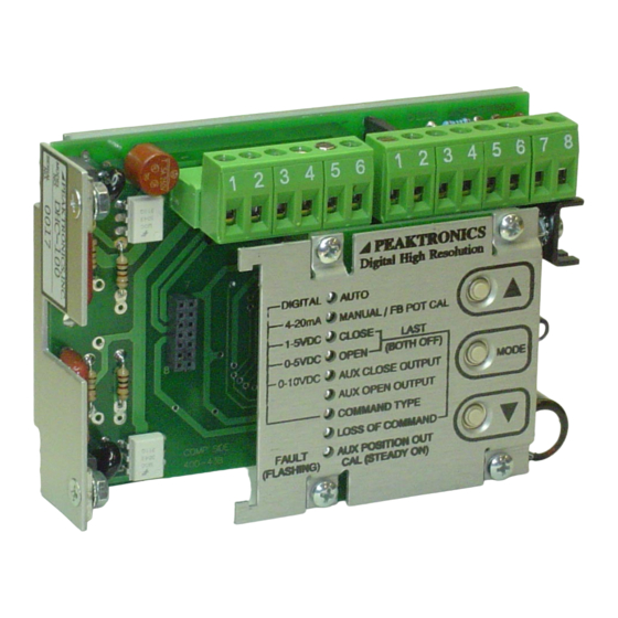
- Page 1 TECHNICAL MANUAL Modbus User's Guide DHC Series Controllers PEAKTRONICS...
- Page 3 PEAKTRONICS Modbus User's Guide - DHC Series Controllers TECHNICAL MANUAL CONTENTS page SECTION I – Overview System Overview DHC Control Panel Control Hierarchy Modbus to PACS Format PACS Parameters Modbus Functions $03 and $06 Modbus Function $08 ...
- Page 4 CONTENTS continued SECTION IV - Modbus Registers OCM-101 PACS Off Line Timer Value Aux Closed Position Aux Open Position PACS Command Input PACS Control Register PACS Timeout Setting Analog Command Input Position Average % Duty Cycle Maximum Deviation Hours of Operation Cycles of Operation...
- Page 5 The scope of this document is to provide a description of digital parameters available in a Peaktronics DHC Series Controller, and how to access those parameters via a Modbus connection. DHC Series Controllers covered by this manual are listed below. New models may get added to this list;...
- Page 6 "The PACS Standard" does not interfere with the DHC's operation or settings. technical manual, available from Peaktronics. Some parameters can be changed, or written, via the bus; these are referred to as Read/Write Parameters. The DHC...
- Page 7 ® PACS parameters can either be Read Only Parameters or shown below: Read/Write Parameters. The following sections describe ® the PACS parameters available in the DHC Series Command Address Data controllers. Table 1 provides a summary of these 1 byte...
-
Page 8: Modbus Function
0005. Section IV describes the meaning of the data bytes MODBUS FUNCTIONS $03 and $06 associated with the Modbus Function. The DHC Series parameters can also be read using Modbus Function $03 and written using Modbus Function $06. Function $03 is restricted to reading a single register;... -
Page 9: Read Only Parameters
SECTION II ® Read Only Parameters PACS If the analog signal is not connected to the DHC ANALOG COMMAND INPUT controller, a reading of 0% is returned. A reading of 0% is 00B0 DOUB also returned when the analog signal is less than 4mA for a 4-20mA signal, and less than 1V for a 1-5V signal. - Page 10 ® PACS Command (RD#B2): POSITION 51 00 B2 00B8 DOUB Returned Data (example): In order to position an automated valve to a desired 09 A0 position (according to the analog or digital command input), the DHC controller uses a feedback potentiometer to monitor the position of the actuator's output shaft that connects to the valve stem.
- Page 11 The bit assignment for each alarm condition is shown associated with the ▼ button when the DHC is below: operated in the manual mode. 7 6 5 4 3 2 1 0 NOTE: When bits 2 and 3 are both set to "1", this X command out of range alarm indicates no motion detected in both directions.
- Page 12 AVERAGE % DUTY CYCLE MAXIMUM DEVIATION 00BE DOUB 00C0 DOUB Duty cycle is a measure of the amount of time an While the command input signal provides the actuator is turned on versus the amount of time it is turned desired position, the actual achievable position will most off.
-
Page 13: Alarm Flags
In the following example, $81 (1000 0001 binary) indicates CYCLES OF OPERATION that an "aux close limit alarm" and a "loss of command" 00C6 QUAD alarm have been detected. While the Hours of Operation parameter can ® PACS Command (RS#CA): provide a measure of how long an actuator/valve has been 50 00 CA in service, the wear on the mechanical components in an... - Page 14 Bit 3 - "motor alarm (M2 stall)" DHC controller, or by using the Aux Closed Bit 3 is set to "1" if the DHC detects a stall in the Position parameter (see Section III). Bit 7 is set to M2 direction. The M2 direction is associated with "1", and the DHC flashes the AUX CLOSE the ▼...
- Page 15 Bits 4 & 5 - "loss of command setting" CONFIGURATION These bits indicate what action the DHC controller 00CC SING will take when it detects a loss of command. Only the values shown below are returned. The Configuration parameter is a SING byte value, where groups of bits are assigned to various DHC controller settings.
- Page 16 No model is assigned a Model will also be "0". Code of $00 or $FF (255 decimal). Model code 13 ($0D) is assigned to a custom product; consult Peaktronics, Inc. for details. SERIAL NUMBER Model Code...
- Page 17 SECTION III ® Read/Write Parameters PACS The DHC controller will set bit 7 of the Alarm AUX CLOSED POSITION Flags parameter to "1" whenever the Position parameter 00D0 DOUB (see Section II) is less than the aux close setting. Bit 7 is set to "0"...
- Page 18 parameter is less than or equal to the aux open setting The DHC can be configured in two ways to use the minus 1%. The aux open position can also be set from the ® Command Input parameter. First, the DHC can PACS DHC control panel using the AUX OPEN OUTPUT mode.
- Page 19 Since bits 0 to 2 allow the bus to run the actuator, of the DHC Series may assign these bits to other the DHC controller must be in the AUTO mode (see control functions.
- Page 20 ® PACS logic commands. The OR command can be used to ® PACS RESET set specific bits to "1", while the AND command can be 00EF SING used to clear specific bits to "0". The EX OR (exclusive-or) command can be used to toggle specific bits between "0" The PACS ®...
- Page 21 $00, unless the user changes their value. Using Unassigned Locations is not recommended since future versions of the DHC Series may assign any of these locations for specific control functions.
-
Page 22: Modbus Registers
SECTION IV Modbus Registers Modbus Function $03 can be used to read the given to subsequent requests from the bus until the OCM- ® parameters described in this section. The read operation is 101 corrects the detected PACS error. restricted to reading one register at a time. Requesting The most significant byte of the data is always ®... - Page 23 ® PACS COMMAND INPUT ANALOG COMMAND INPUT REGISTER ADDRESS (hex) REGISTER ADDRESS (hex) 0003 0006 As a convenience to the user, writing this See page 5 for description of the data bytes. ® parameter also automatically writes the PACS Timeout ®...
- Page 24 32 bit value: identifying whether the OCM-101 being used can access 1. Read Register 13 the additional parameters. Contact Peaktronics, Inc. for 2. Read Register 14 upgrade information and services. 3. If the value returned for Register 14 is zero, then read Register 13 again for the correct value.
-
Page 25: Application Information
The OCM-101 can be configured via the bus to extend this unique node address (1 to 247), while the master device period, although it is not necessary with the DHC Series. does not have a node address. All communications on the... - Page 26 Registers 1, 19, and 20 with function code $03 or $06, the type cannot be selected via the bus. When configured for a request is processed directly by the OCM-101, and response Digital command type, the DHC ignores any analog times are shown below.
- Page 27 50 00 ED Returned Data ® in the DHC. While other PACS commands could be used, note that the DHC Series controllers do ® 6. PACS Command (CD#D8,3500) ® 82 00 D8 0D AC...
- Page 28 Step 3 is similar to step 1, where the bus master be set to a non-zero value since bit 0 is cleared to "0" when sets the node 02 DHC controller's PACS ® a timeout occurs. Command Input to 30.90% ($0C12) followed by A system that intends to use the bus to override a read of the PACS ®...
- Page 29 continues normal operation by reading the Position Position parameter returning a value of 10.03% ($03EB), parameter (00B8 DOUB), which shows a value of 33.62% indicating that the DHC is responding to the override open ($0D22) in step 1 and a value of 33.89% open command value.
-
Page 30: Reference Guide
EOD,d DOUB no ASCII EOQ,d QUAD no ASCII SING 0-255 DOUB 256-511 QUAD 512-767 INCR CHAN ID SING 768-1023 DOUB QUAD Tt,x (channels 0-255) Tt,x (channels 256-511) Tt,x (channels 512-767) TIER Tt,x (channels 768-1023) 1989, 2008 Peaktronics, Inc. -
Page 31: Ascii Conversion Table
APPENDIX B ASCII Conversion Table BINARY ASCII BINARY ASCII BINARY ASCII 0000 0000 0010 1011 0101 0101 0000 0001 0010 1100 0101 0110 0000 0010 0010 1101 0101 0111 0000 0011 0010 1110 0101 1000 0000 0100 0010 1111 0101 1001 0000 0101 0101 1010 0000 0110... - Page 32 PEAKTRONICS, Inc. 1363 Anderson Clawson, MI 48017 Phone (248) 542-5640 FAX (248) 542-5643...
Need help?
Do you have a question about the DHC Series and is the answer not in the manual?
Questions and answers