Table of Contents
Advertisement
Quick Links
PEAKTRONICS
The Peaktronics DHC-400 is a high performance
digital positioner intended to control DC actuators, provid-
ing 450 points of resolution with quarter turn actuators
ranging from 2 sec to 120 sec. The DHC-400 has many
automatic advanced features that will enhance any actuator
while making it easy to install and set up. The DHC-400
can replace a DMC-100 standard size controller in most
applications to upgrade performance.
The simple three button control is used to configure
all parameters the unit needs for a wide variety of applica-
tions, and allows the open and closed positions to be easily
set for direct or reversing acting without any rewiring. The
unit can be configured for various command types (4-
20mA, 1-5V, 0-5V, 0-10V, 2-10V, or a digital command)
and its default operation upon loss of command. The mul-
ticolor LED Fault indication displays up to 15 different
conditions (including "Low Battery Voltage").
Various option modules are easily plugged into the
unit, providing other features such as a position feedback
signal, auxiliary switches, fault relay contact, or digital
communications.
A wide range of data is accessible
through a digital communications module, providing addi-
tional control or information.
•
10 to 30 VDC operating voltage range with motors rated up to 60A locked rotor or 10A run-
ning current.
•
Solid state motor driver with thermal and overcurrent protection provides reliable service be-
yond the life of the actuator motor.
•
Positions to ±0.1° with quarter-turn actuators ranging from 2 sec to 120 sec (with or without a
mechanical brake). Electronic Brake feature can eliminate mechanical brake.
•
Adaptive Control feature continuously adjusts for load and actuator conditions and eliminates
calibration procedures and auto-cal operations.
•
Polarity Detection feature allows direct or reverse acting operation without re-wiring.
•
Stall Detection feature protects actuator motor from a stall condition.
•
Adjustable Motor Current Trip (0-12A) setting limits actuator torque and battery/power sup-
ply current requirements.
•
Electronic Surge Limiting reduces wire size and battery/power supply requirements to 20%
of locked rotor current.
•
Automatic Duty Cycle Control feature prevents motor damage due to overheating and pre-
vents shutdown of a process due to a thermal overload switch.
•
Operating temperature range of 0 to 60°C
DC Digital High-Resolution Controller
FEATURES
DHC-400
U.S. Patent 7,466,100 applies to this product
Advertisement
Table of Contents

Related Manuals for Peaktronics DHC-400


Summary of Contents for Peaktronics DHC-400
- Page 1 DC actuators, provid- ing 450 points of resolution with quarter turn actuators ranging from 2 sec to 120 sec. The DHC-400 has many automatic advanced features that will enhance any actuator while making it easy to install and set up. The DHC-400 can replace a DMC-100 standard size controller in most applications to upgrade performance.
-
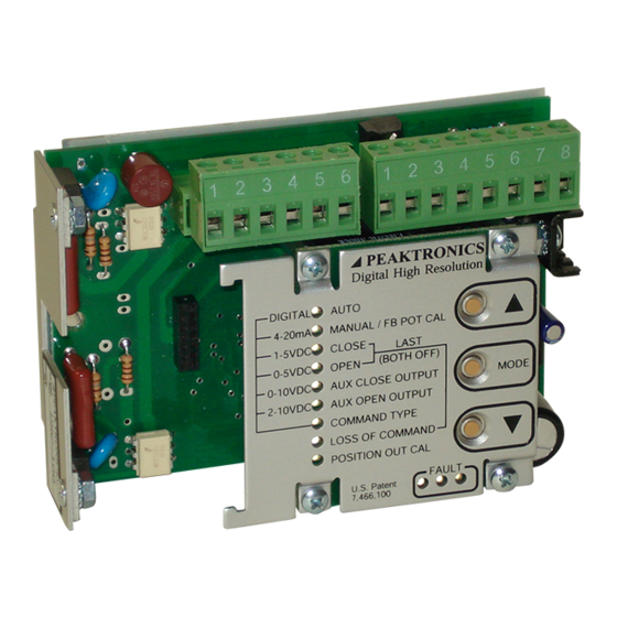
Page 2: Front Panel
DHC-400 OUTLINE PEAKTRONICS Digital High Resolution DIGITAL AUTO ELECTRICAL 4-20mA MANUAL / FB POT CAL CONNECTIONS 1-5VDC CLOSE LAST (BOTH OFF) 0-5VDC OPEN MODE 0-10VDC AUX CLOSE OUTPUT to Feedback Pot 2-10VDC AUX OPEN OUTPUT +2.5V COMMAND TYPE WIPER LOSS OF COMMAND... -
Page 3: Block Diagram
1 while the negative terminal connects to The simple three button control (MODE, ▲, and pin 2. When the DHC-400 is mounted to a metal bracket ▼) allows the user to perform a complete set-up from the or directly to the actuator case, pin 3 provides a terminal unit itself without the need for any instrumentation. - Page 4 7 and 8 must be connected to pin 6 (note, if LOSS OF COMMAND function cannot be used. The pins 7 and 8 are not connected to pin 6, the DHC-400 will MODE button will skip over the LOSS OF COMMAND not be able to control the motor outputs).
-
Page 5: Override Mode
The AUTO function is the normal mode of opera- Controlling the DHC-400 from the Override Input tion for the DHC-400; all the other functions are used to is accomplished by connecting a specific resistance to se- set up the unit. While in AUTO, the unit can be controlled lect a specific operation. -
Page 6: Command Type
Aux Close position, the Aux Close Output indicator potentiometer is at midrange of its rotation. As the actua- will flash. Additionally, the DHC-400 will turn on a relay tor moves, causing the feedback potentiometer to move output on the optional relay module - the output can be... -
Page 7: Fault Indicators
1-5V input), 10.5V (for 2-10V input), or 21mA. If the The DHC-400 detects various fault conditions that DHC-400 detects a loss of command, a fault will be indi- prohibit the unit from controlling the actuator. A combi- cated (see FAULT INDICATORS), and the actuator will... - Page 8 The fault condition will disable the Motor 1 output only, If the Fault relay output turns off (indicating an over volt- and the fault is cleared when the DHC-400 detects a mo- age lasting longer than 1 second), the output will turn back on when the voltage returns to 30V or less.
-
Page 9: Limit Switches
While the Electronic Surge Limiting feature of signal is back in range. See LOSS OF COMMAND for the DHC-400 reduces the high in-rush currents during mo- details. tor starts, the trip setting is used to reduce the current re- quired from the battery/power supply when the motor stalls or encounters an excessive load. - Page 10 DHC-400, and it allows control of the process to be main- DHC-400 motor outputs. In this application, the motor tained without damage to the motor.
-
Page 11: Specifications
DHC-400 SPECIFICATIONS POWER REQUIREMENTS Operating Voltage: 10 to 30 VDC Operating Current, typical: 70mA (not including option module) Fuse Type: 10A TR5 Time Lag 374 (replaceable) COMMAND SIGNAL INPUT Common Mode Voltage (both inputs): -9 to +30 VDC Input Impedance 10.25K ohms (1-5 VDC, 0-5 VDC, 0-10 VDC, 2-10 VDC Input) -
Page 12: Wiring Diagrams
DHC-400 WIRING DIAGRAMS Output Configurations J1-4 MOTOR 1 J1-5 MOTOR 2 THERMAL SWITCH DHC-400 J1-6 LIMIT COMMON (optional) In MANUAL mode, the adjust up button ( ) sets MOTOR 1 positive LIMIT TORQUE and allows the motor to run until LIM... - Page 13 DHC-400 WIRING DIAGRAMS Input Signal Configurations J2-1 J2-1 BAT POS BAT POS J2-2 J2-2 BAT NEG BAT NEG EARTH EARTH J2-3 J2-3 EARTH EARTH NOTE: Arrowed NOTE: Arrowed connections must be connections must be made as close to the made as close to the...
- Page 14 DHC-400 WIRING DIAGRAMS Special Applications XMA-108 J2-1 BAT POS Mechanical Manual Override Switch OPEN Manual 4-20mA Override J7-2 Transmitter 135 ohm Normal Slide Operation Wire DHC-400 Series J2-5 CMD (+) J7-1 J2-4 CMD (-) J2-2 BAT NEG 135 ohm Slide Wire...
- Page 15 DHC-400 WIRING DIAGRAMS Special Applications (continued) J2-1 BAT POS Power DHC-400 J2-2 BAT NEG Source J2-3 EARTH Alternate Connection Preferred Connection OTX-101 (Option Module) mA Feedback Monitor Connecting a position feedback transmitter J2-1 BAT POS Power DHC-400 J2-2 BAT NEG...
- Page 16 1075 NOTES 1) The DHC-400 terminal strip will not accept wire sizes larger than 12 AWG. Use a short run of 12 AWG from the DHC-400 to an auxiliary terminal block when larger wire is needed. 2) If the motor is located some distance from the DHC-400, add this length to the overall wire length;...
Need help?
Do you have a question about the DHC-400 and is the answer not in the manual?
Questions and answers