
Related Manuals for MSTRONIC SOL10D24-SW4-56B1N-IP66


Summary of Contents for MSTRONIC SOL10D24-SW4-56B1N-IP66
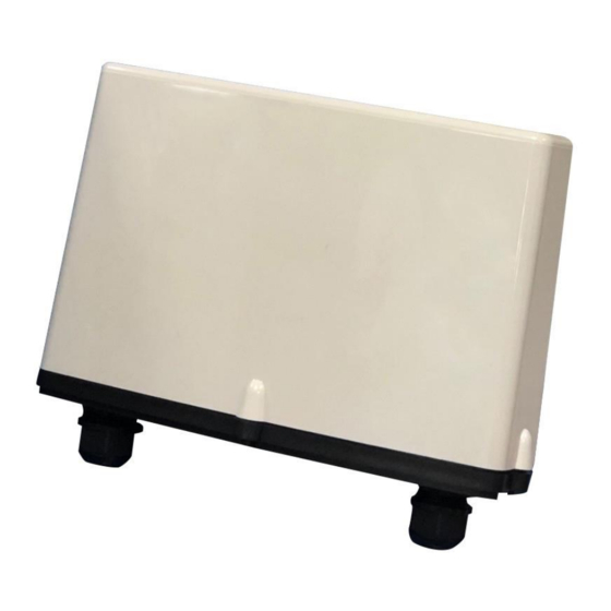
- Page 1 SOL10D24-SW4-56B1N-IP66 Solar Charge Controller + PoE Switch With IP66 Waterproof Box USER’S MANUAL MSTRONIC CO., LTD. Features:...
- Page 2 User’s Manual SOL10D12LFP-SW4-56B1N Features: Solar Input, from solar panel to charge 24V battery Up to four outputs: four 56VDC PoE outputs(total 70W) on RJ45s and one 24VDC output at terminal block Active PoE Output support 802.3at handshake ...
- Page 3 User’s Manual SOL10D12LFP-SW4-56B1N Connection Description: Item Name Descriptions Solar Panel Terminal: used to connect the solar panel. positive electrode Solar Panel Terminal: used to connect the solar panel. negative electrode used to connect the Battery positive. used to connect the Battery negative. SW1~SW4 Connectors: The four RJ45s are used for PoE output, POE OUT/ each port 56V, total 70W.
- Page 4 User’s Manual SOL10D12LFP-SW4-56B1N RJ45 Indicators Description: *SWITCH LED (the right indicator on RJ45) STATUS Description P1~P4 Green A network device is detected (1000Mbps), but no communication activity is detected. Green This port is transmitting to, or receiving package Blinking from another device at 1000Mbps. Yellow A network device is detected (10Mbps or 100Mbps), but no communication activity is...
- Page 5 User’s Manual SOL10D12LFP-SW4-56B1N Operation Guide 1. Connect the battery to the B+ & B- terminal. Make sure the polarities are correctly connected. Sequentially connect the solar panel to S+ & S- terminal. 2. Make sure the battery is properly connected to the unit. If no battery is connected, then no voltage at B+ &...
- Page 6 User’s Manual SOL10D12LFP-SW4-56B1N...
- Page 7 User’s Manual SOL10D12LFP-SW4-56B1N...
- Page 8 User’s Manual SOL10D12LFP-SW4-56B1N...
-
Page 9: Specification
User’s Manual SOL10D12LFP-SW4-56B1N Specification 1.0 INPUT 1.1 Solar Panel 1.2 Input Voltage: 28V ~ 55V 2.0 OUTPUT Model SOL10D24-SW4-56B1N-IP66 DC Output 24V/3A* (rear terminal) (as Bat. Volt.)* PoE Output 1 56V/0.625A (front RJ45) (regulated)* *1 continue 3A,, off @3.2~3.5A *2 the same voltage as battery *3 802.3at x2,or 802.3af x4... -
Page 10: General Description
User’s Manual SOL10D12LFP-SW4-56B1N 4.5 Output Short Circuit Protection: When the rear output terminal or PoE output be short circuit, protection be active, the product stop output and auto-recover when the connector back to normal connection. 4.6 Battery Output Current Limit: The fuse will be burnt when battery output current over 15A 4.7 Load Output Voltage Point: The output voltage on the rear terminal normally is the same as battery. - Page 11 User’s Manual SOL10D12LFP-SW4-56B1N 6. PoE ports pin out: SOL10D24-SW4M-56B1N RJ-45 Output (Data & Power) Symbol Description BI_DA+ Data Pair A+ BI_DA- Data Pair A- BI_DB+ Data Pair B+ +Vdc + BI_DC+ power(+)+Data Pair C+ +Vdc + BI_DC- power(+)+Data Pair C- BI_DB- Data Pair B- -Vdc + BI_DD+...
Need help?
Do you have a question about the SOL10D24-SW4-56B1N-IP66 and is the answer not in the manual?
Questions and answers