Table of Contents
Advertisement
Advertisement
Table of Contents

Subscribe to Our Youtube Channel
Related Manuals for TDK HAL 3900


Summary of Contents for TDK HAL 3900
- Page 1 Joystick Evaluation Platform User Manual HAL 3900 TDK-Micronas GmbH...
-
Page 2: Table Of Contents
Software ............................16 Sensor Configuration ....................... 16 4.1.1 Configuration Note ......................16 4.1.2 Sensor Calibration using HAL 3900 Programming Environment ........16 Evaluation Software Instructions ....................17 Visualisation ..........................19 4.3.1 Magnetic Field Tab (3D Position Detection) ..............19 4.3.2... -
Page 3: Component List
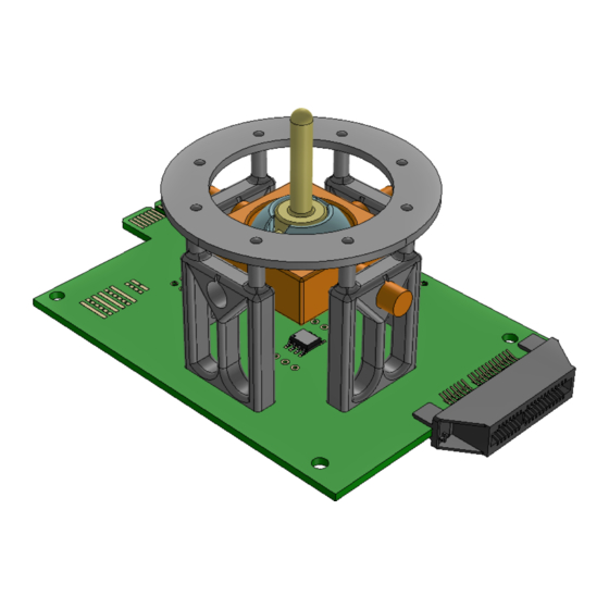
1 Component List 1 X JOYSTICK PCB 2 X RAISED PCB 2 X SIDE PCB 3 X HAL 3900 4 X HOLDER 1 X TOP PLANE TDK-Micronas GmbH Page 3 of 23... - Page 4 1 X REV. LEVER 1 X GIMBAL JOINT 1 X GIMBAL LEVER 2 X 4x10 mm MAGNET 2 X 1x4 HEADER 2 X 1x4 RAISED HEADER 2 X 2x4 HEADER 2X 2-POLE RINGMAGNET 8 X BRASS SCREWS TDK-Micronas GmbH Page 4 of 23...
-
Page 5: Introduction
2.2 Specifications The HAL 3900 is a 3D position sensor based on Hall-effect technology. The sensor includes an array of horizontal and vertical Hall plates based on TDK-Micronas’ 3D HAL technology. The Hall plate signals are first measured by two/three separate A/D-converters (one for each channel), filtered and temperature compensated. -
Page 6: Software
The installation includes the executable of the evaluation software, STL files loaded by the 3D Environment and EEPROM dump files used to program the sensor. More details found in section 4. ************** TDK-Micronas GmbH Page 6 of 23... -
Page 7: Assembly Guide
Joystick module (eg. 3D position and Rotational ) 3.1.2 TDK Magnetic Sensor Programmer V1.x This is the original TDK Magnetic Sensor Programmer, it can only be used in 3D Position Detection. In addition, the Joystick Module has the capapility to accommodate a biphase sensor and establish communication through the RJ25 or using the TDK micro edge card to Dsub-25 adapter board. -
Page 8: Revolving Joint
Figure 8: Revolving Joint complete 3.2.1 3D Position Detection 1. Solder the HAL 3900 on the Joystick PCB at S1 2. Fix one holder on the joystick PCB using the provided brass screws. 3. Place the large rev. joint through the holder 4. - Page 9 Figure 9: Revolving 3D position step 1/ 2/ 3 Figure 10: Revolving 3D position step 4/ 5 Figure 11: Revolving 3D position step 6/ 7 Figure 12: Revolving 3D position step 8 Figure 13: Revolving Lever airgap indicator TDK-Micronas GmbH Page 9 of 23...
- Page 10 Figure 14: Revolving 3D position step 9/ 10 Figure 15: Revolving 3D position step 11 Figure 16: Revolving 3D position complete TDK-Micronas GmbH Page 10 of 23...
-
Page 11: Rotational Position Detection
8. Solder a 0R 0603 resistor on CS Bridge between S4 and CS3 Figure 17: Revolving Rotational step 1 Figure 18: Revolving Rotational step 2 Figure 19: Revolving Rotational step 4 Figure 20: Revolving Rotational step 4 Figure 21: Revolving Rotational step 5 TDK-Micronas GmbH Page 11 of 23... - Page 12 Note: 1. Do not solder a sensor at the face of the side PCB that is unused, if a sensor is already present, remove it. 2. The Position of the HAL 3900 on the "2-pole 360 DEG" side of the side PCB is lower than the "4-pole 180 DEG" side.
- Page 13 4. Solder the Side PCBs to the Joystick PCB at S3 and S4 with the sensor facing the Joystick module. Figure 26: 2 pole magnets Figure 27: XY side PCB assembly ("2-pole 360 DEG" face) Figure 28: XY side PCBs installation Figure 29: XY complete TDK-Micronas GmbH Page 13 of 23...
-
Page 14: Gimbal Joint
9. Push the gimbal lever onto the joint until it locks. 10. Place the top plane. 11. Solder a 0R 0603 on CS Bridge between S2 and CS1. Figure 31: Gimbal Step 1 Figure 32: Gimbal Step 2 - Raised PCB assembly TDK-Micronas GmbH Page 14 of 23... - Page 15 Figure 33: Gimbal Step 3 Figure 34: Gimbal Step 4 Figure 35: Gimbal Step 5 Figure 36: Gimbal Step 6 - magnet installation and position Figure 37: Gimbal Step 6 TDK-Micronas GmbH Page 15 of 23...
-
Page 16: Software
4.1.2 Sensor Calibration using HAL 3900 Programming Environment In case further accuracy is desired, the sensor will need to be calibrated using a TDK SPI Programmer or the TDK-MSP and the HAL 3900 Programming environment. -
Page 17: Evaluation Software Instructions
PCB. 3. Run Joystick_Module_Environment.exe. 4. If the Sensor is used for the first time (or the sensor is not programmed via HAL 3900 PE) a. Navigate to the Configuration Tab Select the programming device you are using TDK SPI Programmer or MSP... - Page 18 Main Tab Configuration Tab TDK-Micronas GmbH Page 18 of 23...
-
Page 19: Visualisation
4.3 Visualisation 4.3.1 Magnetic Field Tab (3D Position Detection) 4.3.2 Magnetic Field Tab (180 or 360 Angular Measurement) TDK-Micronas GmbH Page 19 of 23... -
Page 20: Joystick Tab
4.3.3 Joystick Tab TDK-Micronas GmbH Page 20 of 23... -
Page 21: Appendices
As a result Sensors 1 & 3 are powered by VDD1 and Sensors 2 & 4 are powered by VDD2. When a TDK MSP or TDK SPI Programmer is used the power supply... -
Page 22: Biphase Communication
0603 0R resistor between OUT_SENSx and OUTx. Note each OUTx line supports only one sensor, therefore the maximum allowed number of sensors to be used at once is two. Figure 42: Biphase solder bridge TDK-Micronas GmbH Page 22 of 23... -
Page 23: Joystick Module Schematic
5.2 Joystick Module Schematic TDK-Micronas GmbH Page 23 of 23...
Need help?
Do you have a question about the HAL 3900 and is the answer not in the manual?
Questions and answers