Table of Contents
Advertisement
Quick Links
Evaluation Module User Guide
Chirp Microsystems reserves the right to change
specifications and information herein without notice.
EV_MOD_CH101-01-02
Chirp Microsystems
2560 Ninth Street, Ste 200, Berkeley, CA 94710 U.S.A
+1(510) 640–8155
www.chirpmicro.com
AN-000260
Document Number: AN-000260
Revision: 1.0
Release Date: 01/27/2021
Advertisement
Table of Contents

Related Manuals for TDK EV MOD CH101-01-02


Summary of Contents for TDK EV MOD CH101-01-02
- Page 1 AN-000260 EV_MOD_CH101-01-02 Evaluation Module User Guide Chirp Microsystems Document Number: AN-000260 Chirp Microsystems reserves the right to change 2560 Ninth Street, Ste 200, Berkeley, CA 94710 U.S.A Revision: 1.0 specifications and information herein without notice. +1(510) 640–8155 Release Date: 01/27/2021 www.chirpmicro.com...
-
Page 2: Table Of Contents
AN-000260 Table of Contents SCOPE AND PURPOSE ................................3 EV_MOD_CH101 EVALUATION MODULE BOARD ........................4 ..................................4 SSIGNMENTS ................................4 LECTRICAL PECIFICATIONS ....................................4 CHEMATIC ..................................5 ILL OF ATERIALS CONFIGURATION, PROGRAMMING, AND OPERATION ....................... 6 ..............................6 ONFIGURATION AND ROGRAMMING .................................... -
Page 3: Scope And Purpose
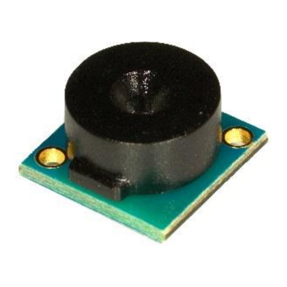
AN-000260 1 SCOPE AND PURPOSE This document details the specification, programming, and operation of an EV_MOD_CH101-01-02 (also referred to as the EV_MOD_CH101 in the remainder of this document) ultrasonic sensor evaluation module. The module board incorporates a CH101 Ultrasonic Sensor device with an 45° field-of-view acoustic housing assembly, a capacitor and an FPC/FFC connector. This evaluation module can perform pitch-catch and pulse-echo range-finding at distances from 4 cm to 1.2m. -
Page 4: Ev_Mod_Ch101 Evaluation Module Board
AN-000260 2 EV_MOD_CH101 EVALUATION MODULE BOARD PIN ASSIGNMENTS Table 1. EV_MOD_CH101 ZIF Connector Pin-Out NAME DESCRIPTION Interrupt output. Can be switched to input for triggering and calibration functions SCL Input. I C clock input. This pin must be pulled up to VDD externally. SDA Input/Output. -
Page 5: Bill Of Materials
AN-000260 Each EV_MOD_CH101 requires its own PROG and INT lines, the remaining connections can be shared. Refer to the CH101 datasheet for additional information. Module connections using a flat flex cable (FFC) are shown in Figure 2-2. Figure 2-2. EV_MOD_CH101 Module Connection (EV_MOD_CH101 acoustic port is facing down) TABLE 2. -
Page 6: Configuration, Programming, And Operation
AN-000260 3 CONFIGURATION, PROGRAMMING, AND OPERATION Please refer to DS-000331 CH101 Datasheet for information on the device’s electrical characteristics. CONFIGURATION AND PROGRAMMING Please refer to the following documents for configuration and programming information: • AN-000154 SmartSonic Hello Chirp Hands-On Document •... -
Page 7: Mechanical Specifications
AN-000260 4 MECHANICAL SPECIFICATIONS TABLE 4. GEOMETRIC DIMENSIONS FOR EV_MOD_CH101-01-02 DIMENSION EV_MOD_CH101-01-02 UNIT Acoustic port hole 0.75 Maximum width 8.15 Module height 5.05 The outer dimensions of the EV_MOD_CH101-01-02 assembly are shown in Figure 4-1. The acoustic port hole has a diameter of 0.75 mm and is in the center of the front face. -
Page 8: Applications
AN-000260 5 APPLICATIONS OBJECT DETECTION Detecting the presence of objects or people can be optimized via software by setting the sensor’s full-scale range (FSR). The user may set the maximum distance at which the sensor will detect an object. FSR values refer to the one-way distance to a detected object. -
Page 9: Beam Pattern
AN-000260 Beam Pattern Beam-pattern plots of the EV_MOD_CH101-01-02 with a 45° FoV acoustic housing module are shown in Figure 5-3. This beam- pattern was measured by placing a 1m flat target at a 30 cm distance from the EV_MOD_CH101 module and recording the ToF amplitude as the sensor is rotated 180°. -
Page 10: Revision History
©2020 Chirp Microsystems. All rights reserved. Chirp Microsystems and the Chirp Microsystems logo are trademarks of Chirp Microsystems, Inc. The TDK logo is a trademark of TDK Corporation. Other company and product names may be trademarks of the respective companies with which they are associated.
Need help?
Do you have a question about the EV MOD CH101-01-02 and is the answer not in the manual?
Questions and answers