Table of Contents
Advertisement
Quick Links
AN-000327
TDK SmartSound One Evaluation Module User
Guide
TDK Corporation
TDK reserves the right to change the detail specifications
Document Number: AN-000327
1745 Technology Drive, San Jose, CA 95110 U.S.A
as may be required to permit improvements in the
Revision: 1.0
+1(408) 988–7339
design of its products.
Release Date: 1/28/2022
www.tdk.com
Advertisement
Table of Contents

Subscribe to Our Youtube Channel
Related Manuals for TDK SmartSound One


Summary of Contents for TDK SmartSound One
- Page 1 AN-000327 TDK SmartSound One Evaluation Module User Guide TDK Corporation TDK reserves the right to change the detail specifications Document Number: AN-000327 1745 Technology Drive, San Jose, CA 95110 U.S.A as may be required to permit improvements in the Revision: 1.0 +1(408) 988–7339...
-
Page 2: Table Of Contents
AN-000327 CONTENTS Overview ....................................3 Key Features ................................... 3 Getting Started ..................................4 Host Computer Setup ................................5 User Hardware Configuration .............................. 6 Reset ....................................6 Mode ..................................... 6 Configuration Header Settings ............................7 Block Diagram ..................................9 Frequently Asked Questions ..............................9 Revision History .................................. -
Page 3: Overview
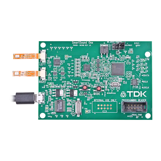
Figure 1. SmartSound One evaluation module with key components identified The SmartSound One Evaluation Module is an easy to use, plug-and-play audio device that is compatible with any TDK MEMS microphone Flexible PCB (FPCB) featuring edge finger pins (see Figures 2-4) and supports the following microphone audio output interfaces: ... -
Page 4: Getting Started
GETTING STARTED SmartSound One uses a micro USB connection to supply power and output audio data. Up to two (of the same audio interface type) TDK FPCB microphones can be connected to the ZIF connectors (shown in Figure 2) to measure the audio output in any audio recording software. -
Page 5: Host Computer Setup
Host Computer Setup SmartSound One comes pre-programmed to allow for plug-and-play functionality out of the box. It is first recommended to supply power to the board with a micro USB cable and verify the blinking LED (reference designator DS5) to ensure successful boot. After plugging into a host like a PC, the board will be recognized as an audio card for recording in any audio recording software such as Audacity, which is a free to use and can be downloaded here https://www.audacityteam.org/. -
Page 6: User Hardware Configuration
Figure 8. LED indications for mode select The mode button shown in Figure 7 selects the type of output interface it expects to see on the FPCB input. SmartSound One starts up in Standby Mode and pressing the ‘MODE’ button scrolls through the other modes in the order listed below: ... -
Page 7: Configuration Header Settings
Pressing the mode button will continue to cycle through the modes in the order listed above. So for example, if the user wants to evaluate a TDK PDM microphone on flex, such as the EV_T5837-FX, then the following steps should be executed:... - Page 8 AN-000327 PWRMODE/PWR_MODE_SEL – Populated by default; populated jumper configures any supported microphone for high quality mode. Depopulating this jumper will configure the microphone in low power mode where applicable. For analog microphones, HQM mode biases the microphone VDD with 2.75V while in LPM the microphone VDD is biased to 1.8V.
-
Page 9: Block Diagram
(i.e 1 Analog and 1 PDM) will likely result in malfunctioning or abnormal behavior and can potentially damage the board. Q: Which TDK MEMS Microphone FPCBs are compatible with this board? A: Only FPCBs with edge connector pins can be plugged into the two on-board ZIF connectors. -
Page 10: Revision History
AN-000327 REVISION HISTORY REVISION DATE REVISION DESCRIPTION 1/18/2022 Initial Release 1/28/2022 Revised typos and updated pictures Page 10 of 11 Document Number: AN-000327 Revision: 1.0... -
Page 11: Compliance Declaration Disclaimer
This information furnished by TDK, Inc. (“TDK”) is believed to be accurate and reliable. However, no responsibility is assumed by TDK for its use, or for any infringements of patents or other rights of third parties that may result from its use. Specifications are subject to change without notice. TDK reserves the right to make changes to this product, including its circuits and software, in order to improve its design and/or performance, without prior notice.
Need help?
Do you have a question about the SmartSound One and is the answer not in the manual?
Questions and answers