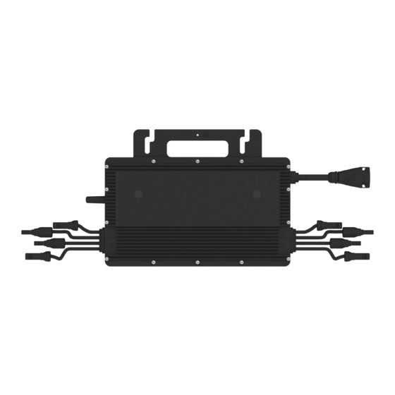
Hoymiles HMS-2000C-4T Series Quick Installation Manual
Microinverter
Hide thumbs
Also See for HMS-2000C-4T Series:
- Quick installation manual (2 pages) ,
- User manual (29 pages) ,
- User manual (31 pages)
Advertisement
Quick Links
1. Accessories
Item
A
ACTrunk Cable, 12/10 AWG Cable
B
M8 x 25 screws (Prepared by the installer)
C
D
E
ACTrunk Port Disconnect Tool
F
G
H
ACTrunk Connector Unlock Tool
*Note:
All accessoriesabove are not included in the package and should be purchased
separately.
2. Installation Steps
The order of Step 1 and Step 2 can be reversed according to your planned needs.
Step 1. Plan and install the Microinverter
A ) Mark the position of each microinverter on the rail, according to the PV module layout.
B ) Fix the screw on the rail.
C ) Hang the microinverter on the
screws, and tighten the screws. The silver
cover side of the microinverter should be
facing the panel.
Note:
1. Thereis an earth wire inside the wire cable and the grounding can be done directly by this wire.
If external grounding is needed,the grounding electrode,as shown on the right, can be used to
bond the
mounting bracket to the racking. Torque each grounding cleat screwto 2 N•m.
2. Install the microinverter and all DCconnections under the PVmodule to avoid direct sunlight, rain
exposure, snow buildup, UV,etc.
3. Leaveat least 2 cm of spacearound the microinverter enclosure to ensure ventilation and heat
dissipation.
4. Mounting torque of the 8 mm screwsshould be 9 N·m.Pleasedo not over-torque.
5. Do not pull or hold the ACcable with your hand. Hold the handle instead.
Step 2. Plan and build the AC Bus Cable
ACTrunk Cable is used to connect the microinverter to distribution box.
A ) Select the appropriate ACTrunk Cable according to the spacing between microinverters. The connector spacing of
the ACTrunk Cable should be close to spacing between microinverters to ensure that they are well-matched. (Hoymiles
provides AC Trunk Cable with different ACTrunk Connector spacing.)
B ) Determine how many microinverters you plan to install on each ACbranch and prepare ACTrunk Connectors
accordingly.
C ) Take out segments of ACTrunk Cable as you need to make AC branch.
1 ) Disassemble the ACTrunk Connector and remove the cable.
- Use the ACTrunk Connector Unlock Tool to
unlock the connector upper cover.
- Loosen the three screws with screwdriver.
Untighten the cap and remove the cable.
2 ) Install the ACTrunk End Cap at one side of ACTrunk Cable (The end of ACTrunk Cable)
- Insert the ACTrunk End cap and screw the
cap back to port, then tighten the cap.
- Plug the upper cover back to the Trunk
connector.
Region: Global AP040511 REV1.1 © 2022 Hoymiles Power Electronics Inc.
HMS-2000C-4TSeries Quick Installation Guide
Description
Grounding Electrode
ACTrunk Connector
ACTrunk Port Cap
AC Trunk End Cap
*Applicable to HMS-1600C/1800C/2000C-4Tmicroinverters
A B C
D
E
F
G
H
Mounting Torque : 9 N·m
4.0±0.5N·m
click
01
Advertisement

Related Manuals for Hoymiles HMS-2000C-4T Series


Summary of Contents for Hoymiles HMS-2000C-4T Series
- Page 1 A ) Select the appropriate ACTrunk Cable according to the spacing between microinverters. The connector spacing of the ACTrunk Cable should be close to spacing between microinverters to ensure that they are well-matched. (Hoymiles provides AC Trunk Cable with different ACTrunk Connector spacing.) B ) Determine how many microinverters you plan to install on each ACbranch and prepare ACTrunk Connectors accordingly.
- Page 2 Guide, and Quick Installation Guide for S-MilesCloud to install will start to generate power in about two minutes. the DTUand set up monitoring system. Product information is subject to change without notice. (Pleasedownload referencemanuals at www.hoymiles.com). Region: Global AP040511 REV1.1 © 2022 Hoymiles Power Electronics Inc.
Need help?
Do you have a question about the HMS-2000C-4T Series and is the answer not in the manual?
Questions and answers