Table of Contents

Related Manuals for Kimo Instruments CPA300


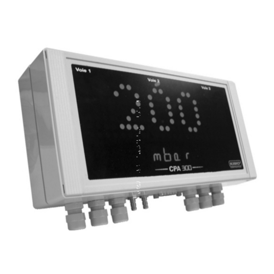
Summary of Contents for Kimo Instruments CPA300
- Page 1 User Manual Presure • Temperature • Humidity • Air Velocity • Air Flow USER MANUAL Configuration CPA300 and THA300 Remote control Remote control MODBUS System MODBUS System Temperature Humidity < THA 300 Pressure CPA 300 >...
-
Page 3: Table Of Contents
Summary 1. Prerequisite ..................1.a - Working principle . - Page 4 Sommaire 10.c - Air velocity correction coefficient input P 23 ..........11.
-
Page 5: A - Working Principle
1. Prerequesite 1.a - Working principle Using remote control / Modbus configuration, you can activate (or deactivate) a channel, change the measuring range, set the set points and time-delay... ® Principle: the configuration options are accessed via folders and sub-folders (similar to Windows ). Access is made via a numerical code (full details in this manual). -
Page 6: Prerequisite
1. Prerequisite 1.b - Output signal selection The Class 300 can output either a voltage or a current signal. Voltage or Current ? Transmitter with 24 Vac/dc power supply Transmitter with 230 Vac power supply (Ref. HV). The on-off switch is located on the left of the terminal block for transmitters with a 24 Vac/dc power supply model and on the right of the relay 1 and 2 for transmitters with a 230 Vac power supply model (Ref.HV). -
Page 7: Modbus Parameters
2. Modbus parameters 2.a - Configuration parameters • commonication speed 19200 Bauds (see page 28 to configure the speed) ..... •... -
Page 8: C - Register Access Security Key
2. Modbus parameters 2.c - Access code to Registers (sequel) • Serial number of sensing element (SPI - CPA 300 / Humidity - THA 300) Modbus code : 1402 Other access codes to different registers are indicated on each function at stage n°2. Shown as this pictogram : Page 4 CPA 300 &... -
Page 9: Activation Code And Access To Functions
3. Activation code and access to functions This step is COMPULSORY for each configuration. To access the transmitter functions, and for safety, you have to first enter a safety code. • Please check that the transmitter is powered on. • If the transmitter displays an error code, please see “Errors Code” section on page 31 Step 1 The first “0”... -
Page 10: F100
F100 4. Display and keypad configuration 4.a - Transmitter channel for infrared remote control You can change the channel number for receiving the signal from the infrared remote control. The advantage is that only one remote control is required to drive several transmitters, and that there is no interference if 2 transmitters are located side by side. -
Page 11: F200
F200 5. Configuring channels and units of measurement Class 300 transmitters have 4 measuring channels. You can activate 1, 2, 3 or 4 channels and select each unit of measurement. Go into configuration mode (see page 5). The folder number displayed Step corresponds to the last configuration folder used. -
Page 12: Analogue Output Management
F300 6. Analogue output management 6.a - Output diagnostics With this function, you can check with a multimeter (or a regulator/display, or a PLC/BMS) if the transmitter outputs are working properly. The transmitter generates a voltage of 0 V, 5 V and 10 V or a current of 4 mA, 12 mA and 20 mA. - Page 13 F300 6. Analogue output management 6.a.2 - Output diagnostics Once the connection of the transmitter to the multimeter (or regulator or PLC/BMS is complete, see page 6), you can carry out the analogue output diagnostics on several check points. Go into configuration mode (see page 5). The folder number displayed Step corresponds to the last configuration folder used.
-
Page 14: B - Analogue Output Settings
F300 6. Analogue output management 6.b - Analogue output settings With this function, you can modify the measuring range of the transmitter, and you can equate the new limits to the analogue output (0-10 V or 4-20 mA). You can enter the measuring range required on your own ! You must enter the values according to the units of measurement selected, not according to the measuring range of the transmitter. - Page 15 F300 6. Analogue output management 6.b.1 - Units of measurement conversion chart Pressure mmH2O inWg mbar mmHg CPA 301 0 à ±100 0 à ±10,2 0 à ±0,401 0 à ±1,00 CPA 302 0 à ±500 0 à ±51,0 0 à ±2,005 0 à...
-
Page 16: Alarm / Relay Settings
F400 7. Alarm / relay settings 7.a - Activation / Deactivation of BEEP alarm The beep alarm (audible alarm) is activated when a set point is reached. For more details on the setpoint settings, see page 20. Step Go into configuration mode (see page 5). The folder number displayed corresponds to the last configuration folder used. -
Page 17: C - Alarm / Relay Functions And Led Colour Codes
F400 7. Alarm / relay settings 7.c - Alarm / relay functions and LED colour codes CPA 300 & THA 300 transmitters have 4 relays visible on the transmitter board with 24 Vac/dc power supply model (2 relays visible on the transmitter board with 230 Vac power supply model Ref.HV). Each relay has one LED to allow real-time checking. -
Page 18: E - Alarm Mode Details
F400 7. Alarm / relay settings 7.e - Alarm mode details 7.e.1 - Definitions Setpoint The setpoint is a limit which, on being reached and/or exceeded , activates an alarm or energizes a relay (in negative security, see page 14 for more details). Time-delay Once the setpoint is reached and/or exceeded, the time-delay postpones the alarm activation (or relay excitation) for a short period (in seconds). - Page 19 F400 7. Alarm / relay settings Configuration N°2 : 1 setpoint, time-delay and rising action activated Measurement Alarm set <T> Time-delay Setpoint 1 <T> <T> <T> Time Relay status Energized Not energized Negative security Relay status Energized Not energized Positive security Configuration N°3 : 1 setpoint, time-delay and falling action activated Measurement Alarm set...
-
Page 20: F - Alarm Mode Selection
F400 7. Alarm / relay settings 7.f - Alarm mode selection Step Go into configuration mode (see page 5). The folder number displayed corresponds to the last configuration folder used. Select the folder “400” and validate with . Select sub-folder Available only on 24 Vac/dc power supply models. -
Page 21: G - Setpoint And Time-Delay Settings
F400 7. Alarm / relay settings 7.g - Setpoints and time-delay setting 7.g.1 - Setpoints Step Go into configuration mode (see page 5). The folder number displayed corresponds to the last configuration folder used. Select the folder “400” and validate with setpoint 1, To configure the select sub-folder... - Page 22 F400 7. Alarm / relay settings 7.g.2 - Time-delay Step Go into configuration mode (see page 5). The folder number displayed corresponds to the last configuration folder used. Select the folder “400” and validate with Select sub-folder Step Available only on 24 Vac/dc power supply models. “406”...
-
Page 23: Pressure Measurement Configuration
F500 8. Pressure measurement configuration 8.a - Pressure measurement integration (CPA 300) The integration coefficient makes an average of the measurements : this helps to avoid any excessive variations and guarantees a stable measurement. New value displayed [((10 - Coef.) x N Value) + (Coef. x former value)] This value is applicable when the variation is less than +/- ( Coef. -
Page 24: Humidity Measurement Configuration
F500 9. Humidity measurement configuration 9.a - Offset setting in humidity and temperature In order to compensate for any longterm drift of the transmitter, you can add an offset to the value displayed by the THA 300 with the EHK 500 reference portable instrument or via the keypad. Function only available on humidity transmitter types THA 300 The EHK 500 is a reference portable instrument (optional) which enables you to adjust at one point the humidity and temperature reading, via the RS 232 connection cable. -
Page 25: Air Velocity Measurement Configuration (Cpa 300 + Sqr)
F600 10. Air velocity measurement configuration 10.a - Temperature compensation You can modify the temperature compensation value. The air velocity and airflow measured with a differential probe (such as Pitot tube, Debimo blade, orifice plate...) depends on the working temperature. Then, it is required to enter the working temperature to get more accurate results. -
Page 26: B - Air Velocity Coefficient Selection
F600 10. Air velocity measurement configuration 10.b - Air velocity coefficient selection (CPA 300) Since the air velocity is calculated from the pressure (on a CPA 300) and from a differential probe, you must enter the coefficient value of the differential probe. For Pitot tubes and Debimo blades, the coefficient is already included in the transmitter. - Page 27 F600 10. Air velocity measurement configuration 10.c- Air velocity coefficient input With this correction coefficient, you can adjust the transmitter according to the air velocity in your installation. Function only available on the transmitter types CPA 300 with SQR option 10.c.1 - How to calculate it ? If the air velocity in your duct is equal to 17 m/s, and if the transmitter indicates 16.6 m/s, then the coefficient to apply is 17 / 16,6 ie 1.024...
- Page 28 F600 11. Airflow measurement configuration 11.a - Selection of duct section type or airflow coefficient 11.a.1 - Working from the section type Function only available on pressure transmitter types CPA 300 with SQR option Step Go into configuration mode (see page 5). The folder number displayed corresponds to the last configuration folder used.
- Page 29 F600 10. Airflow measurement configuration Step With keys, enter the value (from 0 to 3000 mm or 0 to 118.11 inch). Validate with Step The cursor > returns to sub-folders line. • press twice to return to reading mode. • press once to return to another folder selection.
- Page 30 F600 11. Airflow measurement configuration Step With keys, select the unit of measurement (see chart below). Validate with . CPA301, 302 et 303 CPA304 CPA301HV, 302HV et 303HV CPA304HV mmH O mmH O inWg inWg mbar mbar mmHg Step > The cursor returns to sub-folders line.
-
Page 31: Other Functions
12. Other functions 12.a- Activation / deactivation of the RS232 and home bus CPA 300 & THA 300 transmitters have one RS 232 and one RS 485 digital output (Modbus protocol) - optional. With the RS 232, you can display 1 or 2 parameters which are measured by other Class 200 and 300 transmitters, or you can send measurements to be displayed on another Class 300 transmitters. -
Page 32: C - Modification Of Modbus Commonication Speed
12. Other functions 12.c- Modification of Modbus communication speed Step Go into configuration mode (see page 5). The folder number displayed corresponds to the last configuration folder used. Select the folder “100” and validate with Step Select the sub-folder “104” and validate with Step With keys, select a communication speed... -
Page 33: D - Mode Purge
12. Other functions 12.d- Purge mode The purge mode enables to freeze the measurement when being displayed, enables to lock the analogue outputs, and to activate the relay 1, in order to actuate a de-dust system of an air movement conditions system and to activate the relay 2 in order to isolate the transmitter. - Page 34 12. Other functions 12.d.1 -Activation / deactivation of Purge Mode Step Go into configuration mode (see page 5). The folder number displayed corresponds to the last configuration folder used. Select the folder “300” and validate with . Step Select the sub-folder “306” and validate with Step With keys, activate (...
- Page 35 12. Other functions 12.d- Mode Purge 12.d.3 -Frequency Step Go into configuration mode (see page 5). The folder number displayed corresponds to the last configuration folder used. Select the folder “300” and validate with . Step Select the sub-folder “308” and validate with Step With keys , enter the value in minutes of the frequency...
-
Page 36: Error Codes
13. Error codes Code Problem Solution • Check status of the 4 alarms (or 2 alarms for Ref.HV) and 4 channels. Configuration error (alarm(s) set on a non displayed/activated channel) Ex. : the error appears if an alarm is configured on a channel (1, 2, 3 or 4) which is not active. -
Page 37: Functions Recap
14. Functions recap F100 Code Description Available settings Channel n° for IR remote control 0 to 9 Sending data via RS 232 0 or 1 Serial number display Modbus slave number 1 to 255 Modbus communication speed 2400 bds 9600 bds 38400 bds 4800 bds 19200 bds... - Page 38 14. Functions recap F300 Code Description Available settings Analogue output setting on channel 1 0=>0V, 1=>5V, 2=>10V 3=>4mA, 4=>12mA, 5=>20mA Analogue output minimum on channel 1 Analogue output maximum on channel 1 Analogue output setting on channel 2 0=>0V, 1=>5V, 2=>10V 3=>4mA, 4=>12mA, 5=>20mA Analogue output minimum on channel 2 Analogue output maximum on channel 2...
- Page 39 14. Functions recap F400 Code Description Available settings Audible alarm 0 or 1 Relays security 0 (negative) or 1 (positive) Channel selection for relay 1 1=> channel 1, 2=> channel 2, 3 =>channel 3, 4=> channel 4 Channel selection for relay 1 0=>...
- Page 40 14. Functions recap F600 Code Description Available settings 1200 Compensation temperature in °C 1202 Compensation temperature in °F 1206 Air velocity measurement mean Code Differential probe Pitot tube DEBIMO blade Other differential probe 1208 Air velocity coefficient value from 0.0001 to 9.9999 1210 Air velocity correction coefficient from 0.200 to 2.000...
Need help?
Do you have a question about the CPA300 and is the answer not in the manual?
Questions and answers