
Related Manuals for Haier GE APPLIANCES NF80D045S3A


Summary of Contents for Haier GE APPLIANCES NF80D045S3A
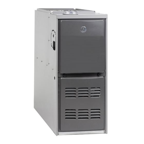
- Page 1 Service NF80DS 80% Downflow Single Stage Manual Constant Torque Gas Furnace READ CAREFULLY. KEEP THESE INSTRUCTIONS 31-5000736 Rev. 0 11-22 GEA...
-
Page 2: Table Of Contents
SERVICE MANUAL NF80DS This is a safety alert symbol and should never be ignored. When you see this symbol on labels or in manuals, be alert to the potential for personal injury or death. Table of Contents WARNING Technical Specifications - NF80DS ......3 Parts Arrangement............6 Improper installation, adjustment, alteration, service Unit Components ............7... -
Page 3: Technical Specifications - Nf80Ds
Technical Specifications - NF80DS MODEL NUMBER GUIDE N F F 80 80 D D S S 4 4 A A XX BRAND MAJOR/MINOR REVISION N - GE CABINET WIDTH PRODUCT A - 14.5 F - FURNACE, GAS B - 17.5 C - 21 AFUE NOMINAL CFM... - Page 4 BLOWER PERFORMANCE DATA CFM @ External Static Pressure - " w.c. Motor Temp Blower Blower Model Size Rise Size Speed (hp) (°F) 0.20 0.30 0.40 0.50 0.60 0.70 0.80 High 1375 1335 1320 1275 1245 1215 1175 Med/High 1145 1120 1075 1045 1000...
- Page 5 ACCESSORIES System Accessory Kit Number Description 11K50 Single Stage Natural to LP Kit 11K45 High Altitude 11M59 14.5" A Width Downflow Combustible Flooring Base 11M60 17.5” B Width 11M61 21.0” C Width Twinning Kit 16W72 Constant Torque Gas Furnace Twinning Kit Note: For vent length and clearances to combustibles, please reference installation instructions.
-
Page 6: Parts Arrangement
Parts Arrangement Secondary Limit Blower Assembly Flue Chase Control Box (includes integrated control, interlock switch and transformer) Blower Access Panel Heat Exchanger Combustion Air Inducer Primary Limit (under combustion air inducer) Gas Valve Burner Box (includes sensor, ignitor Heating Compartment and rollout switches) Access Panel Figure 1. -
Page 7: Unit Components
Circuit Breaker (CB8) Unit Components A 24V circuit breaker is also located in the control box. The switch provides overcurrent protection to the transformer NF80DS unit components are shown in Figure 1. The (T1). The breaker is rated at 3A at 32V. If the current gas valve, combustion air inducer and burners can be exceeds this limit the breaker will trip and all unit operation accessed by removing the upper access panel. - Page 8 1/4” Quick Connect Terminals 120HUM Humidifier 120VAC LINE 120VAC XFMR Transformer 120VAC CIRC Indoor Blower 120VAC Indoor Air Quality Accessory 120VAC NEUTRALS Common 120VAC HUM24 Humidifier 24VAC 3/16” Quick Connect Terminals COOL Cooling Tap 24VAC HEAT Heating Tap 24VAC Continuous Blower 24VAC PARK (no power) Park terminal for unused speed taps Flame Sense...
- Page 9 an inter purge and warm-up time between trials of 35 seconds. After a total of five trials for ignition (including the initial trial), the integrated control goes into Soft Lockout- Flame Failure mode. After a 60-minute reset period, the integrated control will begin the ignition sequence again. Fan Time Control Heating Fan On Time The fan on time of 30 seconds is not adjustable.
- Page 10 Gaskets Internal Flue Pipe Orifice Plate Ignitor Rollout Switches Collector Box Pressure Switch Combustion Air Inducer Sensor Manifold And Gas Valve Figure 6. Heating Components Cooling Fan On Time Flame Rollout Switches (Figure 6) The fan on time is 2 seconds and is not adjustable. Flame rollout switch (S47) is a high temperature limit.
- Page 11 A microamp DC meter is needed to check the flame signal Gas Valve (Figure 6) on the integrated control. The NF80DS uses an internally redundant valve to assure safety shut-off. If the gas valve must be replaced, the same Flame (microamp) signal is an electrical current which type valve must be used.
- Page 12 Remove Sensor Wire from Flame Integrated Control and Sensor Connect Alligator Clip (−) to Flame Sensor Lead Flame Sensor Wire DIGITAL METER Set dial to measure dc microamps Integrated Control Red Collar Indicates Positive Lead Flame Sensor Terminal (-) To flame sensor (+) To Control...
- Page 13 Test 1 Check ignitor circuit for correct resistance. Remove 4-pin plug from control. Check ohms reading across terminals 2 and 4. If value is correct (39 to 70 ohms), this is the only test needed.If the reading on the meter is not correct, (0 or infinity) then a second test is needed.
- Page 14 Combustion Air Inducer (B6) On start-up, the switch senses that the combustion air inducer is operating. It closes a circuit to the integrated All NF80DS units use a combustion air inducer to move control when pressure inside the combustion air inducer air through the burners and heat exchanger during heating decreases to a certain set point.
- Page 15 Blower Compartment Center Blower Wheel in Blower Housing IMPORTANT Each blower is statically and dynamically balanced as an assembly before installation in the unit. NF80DS units are equipped with a constant torque ECM motor. It has a DC motor coupled to an electronic control module both contained in the same motor housing.
- Page 16 Multi−Meter (set to VAC) Multi−Meter (set to VAC) Test 1 Test 3 (if necessary) Turn on power to unit. Check for 120 volts across terminals Check for 120 volts across terminals “CIRC” and “Neutrals” “L” and “N” on input plug P48. If voltage is present continue on the integrated control.
-
Page 17: Placement & Installation
11. Set the thermostat to desired setting. Placement & Installation NOTE: When unit is initially started, steps 1 through 11 may need to be repeated to purge air from gas line. Make sure unit is installed in accordance with installation 12. - Page 18 Gas Pressure Adjustment IMPORTANT Gas Flow (Approximate) In case emergency shutdown is required, turn off the Furnace should operate at least 5 minutes before checking main shut-off valve and disconnect the main power to gas flow. Determine time in seconds for two revolutions of unit.
- Page 19 Proper Combustion High Altitude Furnace should operate a minimum 15 minutes with correct The manifold pressure may require adjustment and manifold pressure and gas flow rate before checking combustion air pressure switch may need replacing to combustion. Take combustion sample beyond the flue ensure proper combustion at higher altitudes.
- Page 20 Proper Ground and Voltage In addition, measure the AC voltage from Line Hot to Line Neutral (spade terminals) on the integrated A poorly grounded furnace can contribute to premature control. See Figure 16. This voltage should be in the ignitor failure. Use the following procedure to check for range of 97 to 132 VAC ground and voltage to the integrated control.
-
Page 21: Typical Operating Characteristics
External Static Pressure Typical Operating Characteristics 1. Tap locations shown in Figure 18. Punch a 1/4” diameter hole in supply and return air Blower Operation and Adjustment plenums. Insert manometer hose flush with inside edge of hole or insulation. Seal around the hose with NOTE: The following is a generalized procedure and does permagum. -
Page 22: Maintenance
Inspect the combustion air inducer and clean if Maintenance necessary. Evaluate the heat exchanger integrity by inspecting At the beginning of each heating season, and to comply the heat exchanger per the AHRI heat exchanger with the GE Appliances Limited Warranty, your system inspection procedure. - Page 23 Clock gas meter to ensure that the unit is operating damage and replace if necessary. at the specified firing rate. Check the supply pressure 14. Reinstall burner box, manifold assembly and burner and the manifold pressure. On two-stage gas furnaces box cover.
- Page 24 gasket orifice plate orifice plate gasket gasket flue chase internal flue pipe internal flue pipe combustion air inducer combustion air inducer ignitor collector box collector box rollout switch heat exchanger heat exchanger pressure switch pressure switch sensor retention rings burners burners manifold and gas valve manifold and gas valve...
-
Page 25: Wiring Diagram
Wiring Diagram 045*3A 070*3A 090*4B 110*5C ‘R’ REQUIRED ON SOME OUTDOOR UNITS PARK TERMINALS ARE UNPOWERED TERMINALS. ALL UNUSED MOTOR LEADS MUST BE WIRED TO A PARK TERMINAL DO NOT USE RED (LOW SPEED) MOTOR LEAD FOR HEATING IF THE RESULTING TEMPERATURE RISE IS OUTSIDE OF THE RANGE SPECIFIED ON THE RATING PLATE. -
Page 26: Troubleshooting: Heating Sequence Of Operation
Troubleshooting: Heating Sequence of Operation HEATING SEQUENCE OF OPERATION ABNORMAL HEATING MODE NORMAL HEATING MODE POWER ON GAS VALVE OFF. COMBUSTION AIR INDUCER OFF. INDOOR BLOWER DELAY OFF. CONTROL SELF-CHECK OKAY? LED SLOW FLASH (RESET CONTROL BY TURNING MAIN POWER OFF.) LED FLASHES CODE 1 - POLARITY IS POLARITY CORRECT? REVERSED. -
Page 27: Troubleshooting: Heating Sequence Of Operation (Continued)
Troubleshooting: Heating Sequence of Operation (Continued) HEATING SEQUENCE CONTINUED 15 SECOND COMBUSTION AIR INDUCER PREPURGE INITIATED BY CLOSED PRESSURE SWITCH. LED FLASHES CODE 13 - LOW LINE VOLTAGE. ONCE VOLTAGE IS ABOVE IGNITOR WARM UP -- 20 SECONDS. IS VOLTAGE ABOVE 70 VOLTS? 75 VOLTS, HEATING SEQUENCE RESTARTS. -
Page 28: Troubleshooting: Cooling Sequence Of Operation
Troubleshooting: Cooling Sequence of Operation COOLING SEQUENCE OF OPERATION POWER ON IGNITION CONTROL MAIN POWER ON. LED FLASHES STEADY - CIRCUIT BOARD FAILURE CONTROL SELF DIAGNOSTIC CHECK. GAS VALVE OFF. COMBUSTION AIR INDUCER OFF. IS CONTROL OPERATING NORMALLY? INDOOR BLOWER OFF WITH NORMAL DELAY. INTERRUPT MAIN POWER TO RESET CONTROL. -
Page 29: Troubleshooting: Continuous Fan / Accessories Sequence Of Operation
Troubleshooting: Continuous Fan / Accessories Sequence of Operation CONTINUOUS FAN / ACCESSORIES SEQUENCE OF OPERATION LED: SLOW FLASH RATE REMAINS UNCHANGED THROUGHOUT SEQUENCE. MANUAL FAN SELECTION MADE AT THERMOSTAT. CONTROL (G) ENERGIZES SYSTEM FAN AT FAN SPEED. EAC TERMINAL IS ENERGIZED. THERMOSTAT CALLS FOR HEAT (W). - Page 30 All specifications and illustrations subject to change without notice and without incurring obligations. Printed in the U.S.A.
Need help?
Do you have a question about the GE APPLIANCES NF80D045S3A and is the answer not in the manual?
Questions and answers