Olympus WM-P1 Series Maintenance & Repair Manual

Olympus WM-P1 Series Maintenance & Repair Manual

Mobile workstations
Table of Contents

Advertisement

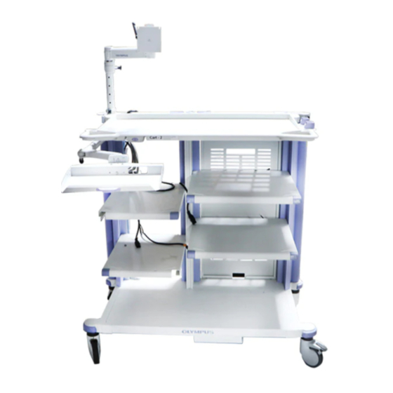
WM--P1 SERIES MOBILE WORKSTATIONS
Issue 20
July 2012
MAINTENANCE & REPAIR MANUAL
WM- -NP1
WM- -WP1
WM- -DP1
OLYMPUS MEDICAL SYSTEMS CORP.
2951 Ishikawa-cho, Hachioji-shi, Tokyo 192-8507, Japan
Fax: (042) 646-2429 Telephone: (042) 642-2111
OLYMPUS EUROPA HOLDING GMBH
(Premises/Goods delivery) Wendenstrasse 14-18, 20097 Hamburg, Germany
(Letters) Postfach 10 49 08, 20034 Hamburg, Germany
Fax: (040)23773-4656 Telephone: (040)23773-0
OLYMPUS AMERICA INC.
3500 Corporate Parkway, P.O. Box 610, Center Valley, PA
Fax: (484) 896-7128 Telephone: (484) 896-5000
KeyMed House, Stock Road, Southend-on-Sea, Essex SS2 5QH, United Kingdom
Fax: (01702) 465677 Telephone: (01702) 616333
OLYMPUS SINGAPORE PTE LTD.
491B, River Valley Road #12-01/04, Valley Point Office Tower, Singapore 248373
Fax: 6834-2438 Telephone: 6834-0010
OLYMPUS (BEIJING) SALES & SERVICE CO,. LTD.
A8F, Ping An International Financial Center, No. 1-3, Xinyuan South Road,
Chaoyang District, Beijing, 100027 P.R.C.
Fax: (86)10-5976-1299 Telephone: (86)10-5819-9000
OLYMPUS MOSCOW LIMITED LIABILITY COMPANY
117071, Moscow, Malaya Kaluzhskaya 19, bld. 1, fl.2, Russia
Fax: (095) 958-2277 Telephone: (095) 958-2245
OLYMPUS AUSTRALIA PTY. LTD.
31 Gilby Road, Mount Waverley, VIC., 3149, Australia
Fax: (03)9543-1350 Telephone: (03)9265-5400
OLYMPUS LATIN AMERICA INC.
5301 Blue Lagoon Drive, Suite 290 Miami, FL 33126-2097, U.S.A.
Fax: (305)261-4421 Telephone: (305)266-2332
OLYMPUS KOREA CO,. LTD.
Olympus-Tower, 114-9 Samseong-Dong, Gangnam-Gu, Seoul 135-090 Korea
Fax: (02)6255-3494 Telephone: (02)6255-3210
18034-0610, U.S.A.
KEYMED LTD.
EKeyMed 2012
K 5070557

Advertisement

Table of Contents
loading

Summary of Contents for Olympus WM-P1 Series

  • Page 1 OLYMPUS SINGAPORE PTE LTD. 491B, River Valley Road #12-01/04, Valley Point Office Tower, Singapore 248373 Fax: 6834-2438 Telephone: 6834-0010 OLYMPUS (BEIJING) SALES & SERVICE CO,. LTD. A8F, Ping An International Financial Center, No. 1-3, Xinyuan South Road, Chaoyang District, Beijing, 100027 P.R.C.
  • Page 2: Change Of Issue Log

    MAINTENANCE & REPAIR MANUAL M- NP1 / WM- WP1 / WM- DP1 WORKSTATIONS CHANGE OF ISSUE LOG When an up- - issued copy of this manual is received, record its receipt on this page. A brief description of the change can be found on the last page of the manual : Summary of Change History. Changes made to the current issue are highlighted in the manual by a vertical line in the right hand margin.
  • Page 3: Table Of Contents

    MAINTENANCE & REPAIR MANUAL WM- NP1 / WM- WP1 WM- DP1 Manual Contents Page Preliminary Material Title Page ..............Change of issue log .
  • Page 4 Chapter 1 Introduction Table of Contents Page Introduction ............Page 4 of 76 Issue 20 : July 2012 WM--P1 SERIES WORKSTATIONS...
  • Page 5: Introduction

    NTRODUCTION This Maintenance and Repair Manual has been produced by KeyMed to enable the repair and servicing of the Olympus WM- - P1 series mobile workstation. Although every effort has been made to ensure that this document is correct and complete, KeyMed cannot be held responsible for the safety or reliability of any equipment which has been repaired other than by suitably qualified personnel.
  • Page 6 Chapter 2 General Information Table of Contents Page General information ........... Page 6 of 76 Issue 20 : July 2012 WM--P1 SERIES WORKSTATIONS...
  • Page 7: General Information

    NFORMATION The Olympus WM- - P1 series mobile workstation is intended for use in medical facilities under the direction of a trained physician, and has been designed to accommodate the Olympus video system center and associated ancillary devices as a practical mobile workstation to facilitate GI endoscopy, endoscopic ultrasound, respiratory and surgical endoscopic procedures.
  • Page 8 Chapter 3 Specifications Table of Contents Page WM- - NP1 / WM- - WP1 series mobile workstations ......WM- - DP1 series mobile workstations .
  • Page 9: Specifications

    PECIFICATIONS WM- NP1 / WM- WP1 series mobile workstations Product name WM--NP1 / WM--WP1 mobile workstation Dimensions (mm) Height: 1370 (scope in lowest position) 2140 (scope in highest position) 1160 (to top tray) 1826 max (with 19” LCD monitor in highest position) Depth: Width: 645 (WM--NP1) 795 (WM--WP1)
  • Page 10 Storage: 23.5--106 kPa (3.4--15.37lbf/in Operation: 70--106 kPa (10.15--15.37lbf/in * UK workstations fitted with Antistatic castors from Oct 2007. WM- T1 series separation transformers Product name Olympus Separation Transformer Identification Market Japan UK, Europe, Rest of the world Model No. MAJ--173...
  • Page 11 Olympus distributor for return and/or collection systems available in your country. The Olympus WM- - P1 series Mobile Workstation and Separation Transformer is manufactured in the UK by KeyMed (Medical & Industrial Equipment) Ltd. Page 11 of 76...
  • Page 12 Chapter 4 Tools & Test Equipment Table of Contents Standard Tools and Test equipment required ....... . Specialised tools required .
  • Page 13: Tools & Test Equipment

    OOLS & QUIPMENT Standard Tools required Flat blade screwdriver Torque driver No 2 Pozidrive tool bit No 3 Pozidrive tool bit 4mm Hex tool bit 8mm Hex tool bit 10mm Hex tool bit 10mm A/F socket 13mm A/F Slim socket Ball driver 6mm A/F Short No 2 Pozidrive screwdriver Torx bit T30...
  • Page 14 Chapter 5 Test and Inspection Table of Contents Page Power supply ............Castor security .
  • Page 15: Test And Inspection

    EST AND INSPECTION Power supply Check the power supply cable and plug for excessive protrusion, twists, deformation or other irregularities. Castor security Check the security of castors at six- - monthly intervals. If loose use castor spanner ( K10005023) fitted to a standard 1/2” drive torque driver to tighten to a torque of 30Nm.
  • Page 16 Chapter 6 Part Replacement Table of Contents Page General ............Blanking caps &...
  • Page 17: Part Replacement

    K10006648 Before replacing any part on the workstation ensure that all mains power is disconnected. Olympus will not be responsible for damage or injury to equipment or personnel, caused by unauthorised modification or repair to this unit. In the interests of safety and good maintenance ensure that fixings are tightened to the torque settings shown in the parts list, illustrated parts list and part replacement chapter.
  • Page 18: Rear Panel Replacement

    Rear panel replacement Each Rear panel is available as a kit which inclues two feet and a finger latch pack. Fit the finger latch as shown in Figure 6-2 and discard the keeper plate, if supplied. WM- - NP1 Rear panel - - part no K10005044. WM- - WP1 Rear panel - - part no K10005045 Refer to Figure 6-2, pull the finger latch to release the top of the rear panel.
  • Page 19: Castor Replacement

    Castor replacement Each workstation has two lockable castors (item 4) and two free castors (item 3). Maintenance/Repair kits available:- - Free castor kit K10004627 Braked castor kit K10004626 Castor free kit WM- - P1 series A/S K10005041 Castor braked kit WM- - P1 series A/S K10005040 Special tool : Castor spanner WM- - P1 series K10005023...
  • Page 20: Remote Switch Replacement

    Remote switch replacement Unplug the Remote switch plug from the separation transformer. Refer to Figure 6-5 for WM- - NP1, Figure 6-6 for WM- - WP1 and Figure 6-7 for WM- - DP1, use a No 2 Pozi drive tool to release four screws (item 77) securing four p clips (item 78).
  • Page 21: Top Tray Replacement Wm- Np1

    Top Tray replacement WM- NP1 Remove all equipment from the top tray (item 14) Refer to Section 6.7 and remove the Remote switch assembly and cable (item 2) from the top tray. Refer to Figure 6-5 to release Support plates WM- - DP1 (item 10) and Top tray (item 14). Using a 6mm allen key unscrew six screws (item 75) with washer crinkle (item 49) and washer (item 45).
  • Page 22: Top Tray Replacement Wm- Wp1

    Top Tray replacement WM- WP1 Remove all equipment from the top tray (item 14) Refer to Section 6.7 and remove the Remote switch assembly and cable (item 2) from the top tray. Refer to Figure 6-6. Using a 6mm allen key unscrew six screws (item 75) with washer crinkle (item 49) and washer (item 45).
  • Page 23: Top Tray Replacement Wm- Dp1

    6.10 Top Tray Replacement WM- DP1 Remove all equipment from the top tray (item 14) Refer to Section 6.7 and remove the Remote switch assembly and cable (item 2) from the top tray. Refer to Figure 6-7 to release Support plates WM- - DP1 (item 10) and Top tray (item 14). Using a 6mm allen key unscrew nine screws (item 75) with washer crinkle (item 49) and washer (item 45).
  • Page 24: Shelf Replacement

    6.11 Shelf replacement Shelf kits : - - MAJ- - 198 WM- - NP1 SHELF KIT (NARROW) - - K10001429 MAJ- - 199 WM- - WP1 SHELF KIT (WIDE) - - K10001430 To remove shelf (item 22) refer to Figure 6-8. If the shelf is to be refitted at the same height make carefull note of the fixing holes used.
  • Page 25: Scope Pole Clamp P1 Series Replacement

    6.12 Scope pole clamp P1 series Refer to Figure 6-1. Blanking caps : Cable port (item 17), Monitor (item 18) and Scope pole (item 19) are a push fit and so require to be carefully prised out of position. Refer to Figure 6-9 Unscrew Handknob (item 6) to release Cable tidy (item 29). Remove the top tray, refer to section 6.8 for WM- - NP1,section 6.9 for WM- - WP1 and section 6.10 for WM- - DP1.
  • Page 26: Power Cable Replacement

    6.15 Power cable replacement The power cable (item 58) may be replaced while the transformer is within the workstation. Disconnect from mains power supply. Disconnect the power cable from the transformer. Disconnect output cables. Refer to Figure 6-10. Using a short No 2 Pozidrive screwdriver release the four screws from cable clamps. FIGURE 6-10 POWER CABLE CLAMP Position a new power cable to ensure that the input connector cable end is 30cm from the clamp.
  • Page 27 Chapter 7 Illustrated Parts List Table of Contents Page WM- - NP1, WM- - WP1 & WM- - DP1 Mobile Workstation ......Page 27 of 76 Issue 20 : July 2012 WM--P1 SERIES WORKSTATIONS...
  • Page 28: Illustrated Parts List

    LLUSTRATED ARTS WM- NP1, WM- WP1 & WM- DP1 MOBILE WORKSTATION FIGURE 7-1 WM- - NP1 & WM- - WP1 PART LOCATION ITEM 93/1 93/3 93/4 93/2 93/5 27 26 2 6Nm WM--DP1 -- 4 Page 28 of 76 Issue 20 : July 2012 WM--P1 SERIES WORKSTATIONS...
  • Page 29 FIGURE 7-2 WM- - DP1 PART LOCATION WM--NP1 WM--WP1 FIGURE 7-3 WM- - NP1 PART LOCATION 4 2.2Nm 2 2Nm 6 20Nm 2 2Nm Page 29 of 76 Issue 20 : July 2012 WM--P1 SERIES WORKSTATIONS...
  • Page 30 FIGURE 7-4 WM- - WP1 PART LOCATION 4 2.2Nm 2 2Nm 4 4Nm 6 20Nm 2 2Nm FIGURE 7-5 WM- - DP1 PART LOCATION 4 2.2Nm 9 2Nm 2 2Nm Page 30 of 76 Issue 20 : July 2012 WM--P1 SERIES WORKSTATIONS...
  • Page 31 FIGURE 7-6 WM- - NP1 & WM- - WP1 PART LOCATION 4 15Nm 2 6Nm Page 31 of 76 Issue 20 : July 2012 WM--P1 SERIES WORKSTATIONS...
  • Page 32 FIGURE 7-7 2.5Nm WM- - NP1 & WM- - WP1 PART LOCATION 2 30Nm/38Nm 2 30Nm/38Nm 4 15Mm Page 32 of 76 Issue 20 : July 2012 WM--P1 SERIES WORKSTATIONS...
  • Page 33 WM- NP1 100V JP p/no K10000284 WM- DP1 100V JP p/no K10003725 WM- NP1 110- 120V US p/no K10000285 WM- DP1 110- 120V US p/no K10003726 WM- NP1 220- 240V UK A/S p/no K10000286 WM- DP1 220- 240V UK A/S p/no K10003727 WM- NP1 220- 240V EU p/no K10000287 WM- DP1 220- 240V EU...
  • Page 34 Item Description Part No Torque Remarks BLANKING CAP CABLE PORT WM- - 260 ....K7503929 BLANKING CAP MONITOR WM- - 260 ....K7504466 BLANKING CAP SCOPE POLE WM- - 260 .
  • Page 35 Item Description Part No Torque Remarks FOOT PUSH- - IN ....... . . K10003425 NP1, WP1- - 2 H, J DP1- - 4...
  • Page 36 Item Description Part No Torque Remarks ACCESSORY KIT FOR WM- - NP1 UK EU ROW ..K10004462 CABLE HANGER - - WITH PIN K10001377 CABLE UNIVERSAL IEC 320 0.8M K3921014 CABLE UNIVERSAL IEC 320 K3921015 INSTRUCTIONS WM- - P1 SERIES ENG K10003436...
  • Page 37 Item Description Part No Torque Remarks ACCESSORY KIT FOR WM- - N/WP1 (NON- - TX) ..K10004791 CABLE HANGER - - WITH PIN K10001377 INSTRUCTIONS WM- - P1 A/S K10004834 ACCESSORY KIT FOR WM- - NP1 EU- - A/S ... . . K10004832 CABLE HANGER - - WITH PIN K10001377 CABLE UNIVERSAL IEC 320 0.8M...
  • Page 38 Item Description Part No Torque Remarks SPARE NUT M8 DOMED NATURAL NYLON ....K10006640 SPACER 18MM OD x 8.2MM ID x 5MM LG ... . . K10006641 LIMITER - - FRONT ( MAJ- - 181 ) .
  • Page 39 Chapter 8 Accessories Illustrated Parts List Table of Contents Page MAJ- - 155 Universal display arm - - LCD ........MAJ- - 179 Keyboard tray sliding .
  • Page 40: Maj- - 155 Universal Display Arm - - Lcd

    LLUSTRATED ARTS IST - CCESSORIES MAJ- 155 UNIVERSAL DISPLAY ARM - LCD FIGURE 8-1 MAJ- - 155 UNIVERSAL DISPLAY ARM - - LCD 2 6Nm MAJ- 155 UNIVERSAL DISPLAY ARM - LCD p/no K7505210 Item Description Part No Remarks Torque BRACKET- - UNIVERSAL DISPLAY LCD .
  • Page 41: Maj- 179 Keyboard Tray Sliding

    MAJ- 179 KEYBOARD TRAY SLIDING FIGURE 8-2 MAJ- - 179 KEYBOARD TRAY SLIDING REMARK 2 8Nm Page 41 of 76 Issue 20 : July 2012 WM--P1 SERIES WORKSTATIONS...
  • Page 42 MAJ- 179 KEYBOARD TRAY SLIDING p/no K10001121 Item Description Part No Remarks Torque RUNNER SUPPORT - - KEYBOARD ..... . . K10001405 TRAY - - SLIDING KEYBOARD .
  • Page 43: Maj- 180 Keyboard Arm - Side Mounted

    MAJ- 180 KEYBOARD ARM - SIDE MOUNTED FIGURE 8-3 MAJ- - 180 KEYBOARD ARM - - SIDE MOUNTED 3 6Nm 4 6Nm Page 43 of 76 Issue 20 : July 2012 WM--P1 SERIES WORKSTATIONS...
  • Page 44 MAJ- 180 KEYBOARD ARM - SIDE MOUNTED p/no K10001112 Item Description Part No Remarks Torque KEYBOARD ARM ASSY (MAJ- - 180) ..... K10004899 DROP DOWN MECHANISM (MAJ- - 180) K10004898...
  • Page 45: Maj- 181 Lcd Monitor Arm

    MAJ- 181 LCD MONITOR ARM FIGURE 8-4 MAJ- - 181 LCD MONITOR ARM 4 2.5Nm LIMITER - - MOVEMENT (MAJ- - 181) SUPPLIED WITH WM- - DP1 WORKSTATION REFER TO ILLUSTRATED PARTS LIST PAGE 7- - 1 & 7- - 11 Page 45 of 76 Issue 20 : July 2012 WM--P1 SERIES WORKSTATIONS...
  • Page 46 62 to 69 SPARE LABEL- - OLYMPUS ........K10003411 SPARE LABEL- - CAUTION .
  • Page 47 MAJ- 181 LCD MONITOR ARM p/no K10001017...continued Item Description Part No Remarks Torque ADHESIVE LOCTITE 243 ......3001857 SPARE SPANNER 7mm A/F x 80mm .
  • Page 48: Maj- 183 Scope Pole Kit

    MAJ- 183 SCOPE POLE KIT FIGURE 8-5 MAJ- - 183 SCOPE POLE KIT 11 25 22 MAJ- 183 SCOPE POLE KIT p/no K10000124 Item Description Part No Torque Remarks POLE SCOPE ........ARM SCOPE .
  • Page 49: Maj- 185 Universal Stowage Container

    MAJ- 185 UNIVERSAL STOWAGE CONTAINER FIGURE 8-6 MAJ- - 185 UNIVERSAL STOWAGE CONTAINER MAJ- 185 UNIVERSAL STOWAGE CONTAINER p/no K10001111 Item Description Part No Torque Remarks UNIVERSAL STOWAGE CONTAINER ..... K10000116 BRACKET- - STOWAGE CONTAINER .
  • Page 50: Maj- - 187 Iv Pole Kit

    MAJ- 187 IF POLE KIT FIGURE 8-7 MAJ- - 187 IV POLE KIT MAJ- 187 IV POLE KIT p/no K10001110 Item Description Part No Torque Remarks IV HANGER (PAINTED) ....... POLE SCOPE .
  • Page 51: Maj- 188 / Maj- 1614 Co

    MAJ- 188 / MAJ- 1614 CO CYLINDER BRACKET KIT FIGURE 8-8 MAJ- - 188 / 1614 CO CYLINDER BRACKET MAJ- 188 MAJ- 1614 MAJ- 188 CO HOLDER 205mm DIA p/no K10001113 MAJ- 1614 CO HOLDER 140mm DIA MAX p/no K10003499 Item Description Part No...
  • Page 52: Maj- 190 Equipment Support Rail

    MAJ- 190 EQUIPMENT SUPPORT RAIL FIGURE 8-9 MAJ- - 190 EQUIPMENT SUPPORT RAIL MAJ- 190 EQUIPMENT SUPPORT RAIL p/no K10001115 Item Description Part No Torque Remarks ACCESSORY BAR ........EQUIPMENT RAIL CLAMP .
  • Page 53: Maj- 192 Side Shelf

    8.10 MAJ- 192 SIDE SHELF FIGURE 8-10 MAJ- - 192 SIDE SHELF MAJ- 192 SIDE SHELF p/no K10001117 Item Description Part No Remarks Torque SIDE SHELF SCREEN PRINTED ......K10001117 INSTRUCTIONS FOR USE MAJ- - 192 .
  • Page 54: Maj- 193, 194, 1611 & 1612 Lockable Drawer

    8.12 MAJ- 193, 194, 1611 & 1612 LOCKABLE DRAWER FIGURE 8-12 MAJ- - 193 & MAJ- - 194 LOCKABLE DRAWER 6 2Nm MAJ- - 193 6 2Nm 6 2Nm MAJ- - 194 6 2Nm Page 54 of 76 Issue 20 : July 2012 WM--P1 SERIES WORKSTATIONS...
  • Page 55 MAJ- 193 LOCKABLE DRAWER (STANDARD) p/no K10001118 MAJ- 194 LOCKABLE DRAWER (DEEP) p/no K10001119 MAJ- 1611 LOCKABLE DRAWER (WIDE) p/no K10001383 MAJ- 1612 LOCKABLE DRAWER WIDE DEEP p/no K10001384 Item Description Part No Torque Remarks DRAWER OUTER ....... . DRAWER SHALLOW- - WELDED .
  • Page 56: Maj- - 196 Rear/Front Panel Kit

    8.13 MAJ- 196 REAR/FRONT PANEL KIT FIGURE 8-13 MAJ- - 196 REAR/FRONT PANEL KIT MAJ- 196 REAR/FRONT PANEL KIT p/no K10001428 MAJ- 1629 RR/FT PANEL KIT- WIDE p/no K10004395 Item Description Part No Remarks Torque FRONT COVER LH ........K10003464 A, B FRONT COVER CENTRE .
  • Page 57: Maj- - 198 Wm- - Np1 Shelf Kit (Narrow)

    8.14 MAJ- 198 WM- NP1 SHELF KIT (Narrow) MAJ- 199 WM- WP1 SHELF KIT (Wide) FIGURE 8-14 MAJ- - 198 WM- - NP1 SHELF KIT (NARROW) MAJ- 198 WM- NP1 SHELF KIT (Narrow) p/no K10001429 MAJ- 199 WM- WP1 SHELF KIT (Wide) p/no K10001430 Item Description Part No...
  • Page 58: Maj- 1600 14" Crt Bracket Kit Maj- 1601 14" Crt Bracket Kit Wide Maj- 1602 20" Crt Bracket Kit Wide

    8.15 MAJ- 1600 14” CRT BRACKET KIT MAJ- 1601 14” CRT BRACKET KIT WIDE MAJ- 1602 20” CRT BRACKET KIT WIDE FIGURE 8-15 MAJ- - 1600 14” CRT BRACKET KIT MAJ- 1600 14” CRT BRACKET KIT p/no K10003525 MAJ- 1601 14” CRT BRACKET KIT WIDE p/no K10003526 MAJ- 1602 20”...
  • Page 59: Maj- 1609 Lcd Arm- Adjustable

    8.16 MAJ- 1609 LCD ARM- ADJUSTABLE FIGURE 8-16 MAJ- - 1609 LCD ARM- - ADJUSTABLE 4 1.5Nm 39 38 Page 59 of 76 Issue 20 : July 2012 WM--P1 SERIES WORKSTATIONS...
  • Page 60 MAJ- 1609 LCD ARM - ADJUSTABLE p/no K10004880 Item Description Part No Remarks Torque LCD ARM ......... . ADAPTOR PLATE VESA MOUNT .
  • Page 61: Maj- 1610 Lcd Manoeuvring Handle

    8.17 MAJ- 1610 LCD MANOEUVRING HANDLE FIGURE 8-17 MAJ- - 1610 LCD MANOEUVRING HANDLE MAJ- 1610 LCD MANOEUVRING HANDLE p/no K10003688 Item Description Part No Remarks Torque LCD MANOEUVRING HANDLE- - WELDED ....K10003665 LABEL- - WARNING TRIANGLE 12mm HIGH .
  • Page 62: Maj- 1613 Universal Display Arm (Crt)

    8.18 MAJ- 1613 UNIVERSAL DISPLAY ARM (CRT) FIGURE 8-18 MAJ- - 1613 UNIVERSAL DISPLAY ARM (CRT) Page 62 of 76 Issue 20 : July 2012 WM--P1 SERIES WORKSTATIONS...
  • Page 63 MAJ- 1613 UNIVERSAL DISP ARM CRT IPF p/no K10001444 Item Description Part No Remarks Torque PLATE- - UNIVERSAL DISPLAY ......K10000711 SPACER- - UNIVERSAL DISPLAY CRT .
  • Page 64: Maj- 1620 14" Crt Mount (Narrow) Maj- 1621 20" Crt Mount (Narrow) Maj- 1622 14" Crt Mount (Wide) Maj- 1623 20" Crt Mount

    8.19 MAJ- 1620 14” CRT MOUNT (NARROW) MAJ- 1621 20” CRT MOUNT (NARROW) MAJ- 1622 14” CRT MOUNT (WIDE) MAJ- 1623 20” CRT MOUNT FIGURE 8-19 CRT MOUNT 7, 20, 26, 33 20 Nm 13, 22 , 30 1, 14 2, 14 MAJ- 1620 14”...
  • Page 65 Item Description Part No Torque Remarks HANDLE BLACK ANODISED ......K3921385 CABLE TIE REL + BASE FIR TREE ..... . . 3006719 DETENT RING PIN .
  • Page 66: Maj- 1624 Nurses Control Panel Arm

    8.20 MAJ- 1624 NURSES CONTROL PANEL ARM FIGURE 8-20 MAJ- - 1624 NURSES CONTROL PANEL ARM MAJ- 1624 NURSES CONTROL PANEL ARM - pt/no K10003563 Item Description Part No Torque Remarks SCREW M4 x 10 PHILLIPS FLANGE PAN HD ....K3921655 SCREW M6 x 16 SKT BUTT HD .
  • Page 67: Maj- 1625 Eum30 Keyboard

    8.21 MAJ- 1625 EUM30 KEYBOARD FIGURE 8-21 MAJ- - 1625 EUM30 KEYBOARD 2, 9 2 0,2 -- 0,3 Nm MAJ- 1625 EUM30 KEYBOARD p/no K10004262 Item Description Part No Torque Remarks WELDED TRAY ASSY (WM- - W260) ..... . . K7504684 FINGER PULL .
  • Page 68: Maj- 1626 Eus Arm Mount

    8.22 MAJ- 1626 EUS ARM MOUNT FIGURE 8-22 Fixing to top tray Fixing to frame MAJ- 1626 EUS ARM MOUNT KIT p/no K10004158 Item Description Part No Remarks Torque 1 to 5 SPARE SCREW M6 x 12 HEX SKT BUTT HD ..... 3920326 WASHER CRINKLE M6 .
  • Page 69: Maj- 1627 Eu- C60/200 Shelf Kit

    8.23 MAJ- 1627 EU- C60/200 SHELF KIT FIGURE 8-23 MAJ 1627 EU- - C60/200 SHELF KIT 12 2Nm Page 69 of 76 Issue 20 : July 2012 WM--P1 SERIES WORKSTATIONS...
  • Page 70 MAJ- 1627 EU- C60/2000 SHELF KIT p/no K10004199 Item Description Part No Remarks Torque SLIDING TRAY ........K10004381 FIXED TRAY WELDED .
  • Page 71: Maj- 1628 Nurses Control Panel Arm

    8.24 MAJ- 1628 NURSES CONTROL PANEL ARM FIGURE 8-24 MAJ- - 1628 NURSES CONTROL PANEL 4 1.5Nm 1 20 4 6Nm 2 3Nm 2 3Nm MAJ- 1628 NURSES CONTROL PANEL ARM p/no K10004881 Item Description Part No Torque Remarks MOUNTING PLATE ........K10004944 SPARE SPARE...
  • Page 72 MAJ- 1628 NURSES CONTROL PANEL ARM p/no K10004881...continued Item Description Part No Remarks Torque SPARE SPARE SPRING NUT M6 ........K7503840 SPARE SPARE...
  • Page 73: Maj- 1630 Video/Scope Cable Bracket

    8.25 MAJ- 1630 VIDEO/SCOPE CABLE BRACKET FIGURE 8-25 MAJ- - 1630 VIDEO/SCOPE CABLE BRACKET MAJ- 1630 VIDEO/SCOPE CABLE BRACKET p/no K10004449 Item Description Part No Torque Remarks BRACKET CABLE (VIDEO/SCOPE) ..... . K10004448 BRACKET VIDEO/SCOPE .
  • Page 74: Maj- 1631 Plug Block Kit - Eu

    8.26 MAJ- 1631 PLUG BLOCK KIT - EU FIGURE 8-26 MAJ- - 1631 PLUG BLOCK KIT - - EU 3, 6 0.2m Adaptor brackets supplied with Plug block item 12 MAJ- 1631 PLUG BLOCK KIT - EU p/no K10004515 Item Description Part No Remarks...
  • Page 75: Maj- - 1635 Maj- - 1635 Eus Connector Holder

    8.27 MAJ- 1635 EUS CONNECTOR HOLDER FIGURE 8-27 MAJ- - 1635 EUS CONNECTOR HOLDER MAJ- 1635 EUS CONNECTOR HOLDER - p/no K10011159 Item Description Part No Remarks Torque MAJ- - 1635 EUS CONNECTOR BRACKET S/P ....K10011158 BUSH .
  • Page 76: Summary Of Change History

    SUMMARY OF CHANGE HISTORY Change Date Issue No. Brief description of change(s) Request No. Effective 01663 August 2010 This manual has been re- - issued in its entirety at issue 17 to incorporate some changes to the content and change the format of the manual. Format: The page number stream has been modified to run consecutively.

This manual is also suitable for:

Wm-np1Wm-wp1Wm-dp1

Table of Contents