Table of Contents
Advertisement
Advertisement
Table of Contents

Related Manuals for Topdon AL500B


Summary of Contents for Topdon AL500B
- Page 1 AL500B USER MANUAL OBD-II Scanner & Battery Tester...
-
Page 2: Table Of Contents
CONTENTS ...... Manual Support in Other Languages ...... Safety Is Always the First Priority! ...... Section 1 What's in the Box? ...... Section 2 Product Overviews ...... Section 3 Using the Scan Tool ...... Section 4 Battery Test ...... Section 5 Review ...... -
Page 3: Manual Support In Other Languages
PLEASE, CAREFULLY READ AND MAKE SURE YOU FULLY UNDERSTAND ALL THE SAFETY INSTRUCTIONS AND MESSAGES ON THIS MANUAL. Given the AL500B is a combination of OBD-II scanner and battery tester, YOU MUST READ THE VEHICLE'S SERVICE MANUAL, THE BATTERY MANUFACTURER’S SPECIFIC... - Page 4 ONLY OPERATE THE TEST IN A WELL- VENTILATED AREA since the vehicle produces carbon monoxide, a toxic and poisonous gas, and particulate matter when the engine is running. ALWAYS WEAR APPROVED SAFETY EYE PROTECTION to prevent damage from sharp objects and caustic liquids. ALWAYS BE AWARE OF MOVING PARTS (such as coolant fans, pulleys, belts) since they spin or turn at high speeds when the engine is...
-
Page 5: Section 1 What's In The Box
IMMEDIATELY. If battery acid gets on your skin or clothing, WASH IT IMMEDIATELY WITH A SOLUTION OF WATER AND BAKING SODA. SECTION 1 WHAT'S IN THE BOX? AL500B Battery Test Cable with Clamps OBD-II 16-pin Connector Cable Mini-USB Data Transfer Cable Carrying Bag... -
Page 6: Section 2 Product Overviews
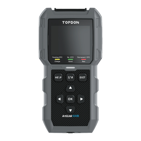
SECTION 2 PRODUCT OVERVIEWS Controls & Connections 1. Display: The 2.8" colored screen shows menus, submenus, test results, specific functions, monitor status info. For further details, please refer to the following section Main Menu & Home Screen Icons. (See Figure 2.1.1) Figure 2.1.1 EN | 7... - Page 7 2. Indicator Status: The 3-color (green. yellow, red) LED indicator shows the OBD-II diagnostic and battery test results. The Definition of 3-Color Indicator ● Green LED: Indicates that all on-board systems are "OK" operating normally. There is no DTC stored in the ECU.
- Page 8 8. Mini-USB Port: This port is for you to connect to the PC to transfer the diagnostic or battery test report. (See Figure 2.1.3) ● There is no built-in battery inside of the AL500B, so no need to charge it. The Mini-USB port is only for data transformation.
- Page 9 Figure 2.1.5 Main Menu & Home Screen Icons Once the AL500B is connected to the power source (through OBD-II Diagnostic Cable or Battery Test Cable), the 2.8" color LCD screen will light up and display the main menu (See Figure 2.2.1). To help you understand each icon, please read the following content carefully.
- Page 10 CCA, internal resistance, state of charge, state of health, etc. For detailed info, please go to Section 4 Figure 2.2.3 Once I/M is selected, the AL500B will automatically communicate with on-board systems to diagnose the readiness status of emission-related systems, monitors, and components.
- Page 11 The LOOKUP (See Figure 2.2.6) refers to the DTC lookup which gives you the specific definitions of DTCs. Figure 2.2.6 After connecting the AL500B to the PC through a Mini USB cable, you can access and print the test report through the PRINT (See Figure 2.2.7) function.
- Page 12 OBD, live data stream, I/M readiness, and the notes of the PRINT function. Figure 2.2.9 The Info (See Figure 2.2.10) provides you with the information of the AL500B you purchased, including software version, serial number, register code, etc. Figure 2.2.10 EN | 13...
-
Page 13: Section 3 Using The Scan Tool
SECTION 3 USING THE SCAN TOOL Preparation ● DO NOT CONNECT THE SCAN TOOL TO THE VEHICLE WHILE THE VEHICLE IS ON. Doing so could cause damage to the scan tool or vehicle's electronic components. ● Retrieving the DTCs is only one part of on-board diagnostic. - Page 14 refer to the vehicle's service manual, or contact us with specific vehicle information (e.g., VIN). Figure 3.1.2 3. Properly connect the scan tool to the DLC (See Figure 3.1.3). The cable connector is keyed and will only fit one way. ●...
- Page 15 ● The method of ignition varies by vehicle model. Please refer to the service manual. Figure 3.1.4 Figure 3.1.5 5. When the scan tool is properly connected to the DLC, the units will start initializing and present you with the main menu interface.
- Page 16 Figure 3.2.1 2. To retrieve the DTCs, please select Read Codes (See Figure 3.2.2), and press [OK]. The scan tool will communicate with ECU and present you with DTCs. Figure 3.2.2 Procedure for Clearing the DTCs 1. Select the Erase Codes Icon (See Figure 3.3.1), and press [OK] ●...
- Page 17 out. Once confirmed, the emission-related data stored in the ECU will be reset or cleared, WHICH IS NOT RETRIVEABLE. ● DO NOT START UP THE ENGINE WHILE CLEARING THE CODES. Figure 3.3.1 2. After determining that all repairs have been completed, press [OK] to clear or reset the emission-related diagnostic data.
- Page 18 I/M Readiness The I/M Readiness (See Figure 3.4.1) checks whether or not the various emissions-related systems on the vehicle are operating properly, and are ready for Inspection and Maintenance testing. It can also be used to confirm that the repair has been performed correctly, and/or to check for monitor run status after the repair has been performed.
- Page 19 Figure 3.4.3 To help you understand the test results, we have listed the full names of the abbreviated phrases below. You can also press the HELP (See Figure 3.4.4) shortcut button to check the full names of components and monitors. ●...
- Page 20 Data Stream The AL500B allows you to view or record Live Data Stream (See Figure 3.5.1) which includes values (volts, rpm, temperature, speed, etc.) and system status information (open-loop, closed-loop, fuel system status, etc.) generated by the various vehicle sensors, switches, and actuators.
- Page 21 Figure 3.5.2 2. Select Items Press [OK] to select the data stream you want to check. (There is no limit to the number of data streams you can select.) After selecting the data streams, press [EXIT] to access the results instead of [OK]. ●...
- Page 22 Figure 3.5.4 Freeze Frame When the MIL is set to "ON", The Freeze Frame Data (See Figure 3.6.1) that is present in the engine or emission-related system is stored in computer memory for later retrieval. This information shows the status of the fuel system (closed or open loop), engine load, cooling water temperature, fuel trim value, MAP vacuum, engine RPM, etc.
- Page 23 Press [OK] to check the freeze frame stored in the ECU. (See Figure 3.6.2) ● Once the DTCs are erased, the freeze frame will also be cleared. Figure 3.6.2 O2 Sensor Test The O2 Sensor Test (See Figure 3.7.1) lets you retrieve and view O2 sensor monitor test results.
- Page 24 Press [OK] to select the oxygen sensor you want to view "Bank 1-Sensor 1" or "Bank 1-Sensor 2" .(See Figure 3.7.2) Figure 3.7.2 On-Board Monitoring This On-Board Monitoring (See Figure 3.8.1) retrieves test results for emission-related powertrain components and systems (such as catalyst monitor B1, VVT monitor Bank 1, Sensor Heater, etc.) that are not continuously monitored.
- Page 25 Press [OK] to select the monitors you want to view. (See Figure 3.8.2) Figure 3.8.2 EVAP System This EVAP System (See Figure 3.9.1) function initiates a leak test for the vehicle's EVAP system. Figure 3.9.1 Select EVAP System and press [OK] to conduct leak test. (See Figure 3.9.2)
- Page 26 Figure 3.9.2 Vehicle Information To view the vehicle information, select "Vehicle Information" (See Figure 3.10.1) and then press [OK]. Figure 3.10.1 This function retrieves information (provided by the manufacturer) from the vehicle's on-board computer (See Figure 3.10.2). It includes: ● VIN (Vehicle Identification Number) ●...
-
Page 27: Section 4 Battery Test
TERMINAL AND BLACK CLAMP TO THE NEGATIVE (–). ● ALWAYS DISCONNECT THE NEGATIVE CABLE FROM THE BATTERY FIRST AND RECONNECT IT LAST. ● The AL500B only supports Lead-Acid Batteries. LITHIUM-ION BATTERIES ARE NOT SUPPORTED! ● ALWAYS WEAR EYE PROTECTION EQUIPMENT avoiding direct skin or eye contact with corrosive liquids. - Page 28 Setup & Connection Where is the battery of a car located? 1. Most models hold the battery in the engine bay, under the hood, in one of the front corners. See battery location ① and ② in Figure 4.1.1. 2. To balance uneven weight distribution, some manufacturers hold the engine in the trunk.
- Page 29 Figure 4.1.2 How to understand the battery lable? Let's use Figure 4.1.3 as an example: Manufacturers Battery Part No. Type 80Ah 12v (SAE) Reserve Capacity Voltage CCA in USA Figure 4.1.3 1. Reserve Capacity: 80Ah The Reserve Capacity is a time measurement that explains how long a fully-charged battery can deliver 25 amps current in an 80°F- environment, before the battery is discharged and drops down to 10.5 volts.
- Page 30 ● Flooded Lead Acid Battery (Wet): This is the oldest/most common car battery type, also known as "SLI battery." The Flooded Battery is usually made of 6 cells with a liquid electrolyte solution of sulfuric acid and water that needs to be topped off periodically.
- Page 31 3. Voltage: 12V When fully charged, automotive batteries should measure at 12.6 volts (See Figure 4.1.5). However, this measurement should be from 13.7 to 14.7 when the engine is running. If the battery tester reads less than this standard, it means that the battery's resting voltage is weak.
- Page 32 3. Once the clamps are properly connected, the battery tester will power on automatically and be ready to conduct tests. (Red) (Black) Figure 4.1.6 Battery Test ● The battery testing function is only applicable for 12V lead-acid batteries (24V are not supported). 1.
- Page 33 Figure 4.2.2 3. Select the corresponding battery type and press [OK] (See Figure 4.2.3). The specific battery type is usually listed on the battery label. Figure 4.2.3 4. Select the corresponding battery standard and press [OK] (See Figure 4.2.4). The specific battery standard will also be listed on the battery label.
- Page 34 ● Please refer to the following table for specific battery standards and test ranges. The battery test analyzer will test each battery according to the selected system and rating. Measurement Measurement Description Standard Range Cold Cranking Amps, specified by SAE & BCI, most 100-2000 frequently used value for starting battery at 0°F(-18°C)
- Page 35 5. Input the CCA by using the arrow keys (Up & Down) and press [OK] to start the test (See Figure 4.2.5). Figure 4.2.5 6. The test result will appear shortly on the tool's display (See Figure 4.2.6). Figure 4.2.6 State of Health, State of Charge, and Internal Resistance: ●...
- Page 36 ● Internal Resistance: The internal resistance is the opposition to the current flow presented by the cells and the battery itself, generating heat. Its electronic resistance and ionic resistance directly impact this indicator. Cranking Test ● BEFORE THE CRANKING TEST, THE ENGINE AND ALL OTHER ACCESSORY LOADS MUST BE OFF WHEN PERFORMING CRANKING TESTS IN ORDER TO ENSURE ACCURATE RESULTS.
- Page 37 3. The test results will appear on the display. Please refer to the chart below to understand the test results. Item Cranking Voltage Conclusion <9.6V Cranking Voltage Low 9.6V≤, and <10.7V Normal ≥10.7V Good Cranking Time and Cranking Voltage: ● The Cranking Time refers to the time it takes for a vehicle to start the engine.
- Page 38 5 seconds. Figure 4.4.2 3. The AL500B will prompt you to increase the RPM to 2500 and hold. Do as requested and press [OK] to continue. Figure 4.4.3 4.
- Page 39 5. The test results will appear on the display. Please refer to the chart below to understand the test results. Item Voltage(V) Conclusion No Output <12.8V Charging Low 12.8V≤, and <13.2V Charging Normal 13.2V≤, and <15V Charging High ≥15.0V Loaded/Unloaded Voltage and Ripple: ●...
-
Page 40: Section 5 Review
SECTION 5 REVIEW The REVIEW function saves the diagnostic reports and test results automatically. This way, you can go back and check previous data at any time. ● You can turn off this function on the tool's settings (Please refer to Section 8 for detailed information). 1. - Page 41 ● Up to 15 diagnostic records can be stored under each item. You can select and delete previous reports if desired. Figure 5.1.3 4. Select Review BT and press [OK]. Eight options will appear on screen (See Figure 5.1.4) - including reviewing battery tests, cranking tests, charging tests, and system test results.
-
Page 42: Section 6 Dtc Lookup
SECTION 6 DTC LOOKUP DTC LOOKUP is a function that can provide you with definitions of DTCs after inputting the codes. To understand the DTCs, see figure 6.1.1. OBD2 DTC EXAMPLE P0201 - Injector Circuit Malfunction, Cylinder 1 P 0 2 0 1 B - Body C - Chassis P - Powertrain... - Page 43 Press [OK] to confirm. Figure 6.1.2 2. We're going to take a fault code P0111 as an example (See Figure 6.1.3). The AL500B gives you the definition of the code (Intake air temperature sensor 1 circuit range/ performance bank 1).
-
Page 44: Section 7 Print
3. Log in to the Topdon account. ● If it is the first time you purchase the Topdon product and you don't have an account, please register with your email. -
Page 45: Section 8 Setting
Figure 8 . 1.2 2. To change the menu's language, select Language and press [OK]. Then select your preferred language (See Figure 8.1.3) and press [OK] again. ● The AL500B offers 7 languages (English, French, Spanish, German, Italian, Portuguese, and Japanese). - Page 46 Figure 8 . 1.3 3. To change the unit of measure, select Unit of Measure and press [OK]. You can select Imperial or Metric (See Figure 8.1.4). Figure 8 . 1.4 4. To change the Record Mode's setting (See Figure 8.1.5), select Record Mode and Press [OK].
-
Page 47: Section 9 Help
5. To change the Beeper's setting select Beeper and press [OK]. The Beeper is on by default, but you can turn it off by pressing [OK] again. Figure 8 . 1.6 SECTION 9 HELP The HELP function provides you the operating instructions for the scan and the additional information you may need to perform OBDII diagnostics and battery tests. - Page 48 Figure 9.1.2 3. Select ABOUT DATASTREAM (See Figure 9.1.3), and press [OK] to view the definition of each datastream item. Figure 9.1.3 4. Select PRINT HELP (Figure 9.1.4) and press [OK] to view the instructions for printing test reports. Figure 9.1.4 EN | 49...
-
Page 49: Section 10 Info
5. Select I/M READINESS (See Figure 9.1.5) and press [OK] to view the full meaning of the abbreviated phrases that describe the monitors and components. Figure 9.1.5 SECTION 10 INFO Select INFO (See Figure 10.1.1) and press [OK] to view the scan tool's hardware version, software version, serial number, registration code and web support information. -
Page 50: Section 11 Update
2. To update the scan tool, please connect the tool to PC through USB-Mini cable. 3. Open the PC Suit application and log in to the Topdon account. ● If it is the first time you purchase the Topdon product and you don't have an account, please register with your email. -
Page 51: Section 13 Faq
Some DTCs can only be erased after you follow all of these steps. Q: Can the AL500B test the battery installed in the vehicle? A: Yes, this tool supports both in-vehicle and out-of-vehicle testing. -
Page 52: Section 14 Warranty
12 months from the date of purchase (Warranty Period). For the defects reported during the Warranty Period, TOPDON will either repair or replace the defective part or product according to its technical support analysis and confirmation. TOPDON shall not be liable for any incidental or consequential damages arising from the device's use, misuse, or mounting. -
Page 53: Section 15 Fcc
SECTION 15 FCC This device complies with Part 15 of the FCC Rules. Its operation is subject to the following two conditions: (1) this device may not cause harmful interference, and (2) this device must accept any interference received, including interference that may cause undesired operation. Note: This equipment has been tested and found to comply with the limits for a Class B digital device, pursuant to Part 15 of the FCC Rules. - Page 54 86-755-21612590 1-833-629-4832 (NORTH AMERICA) EMAIL SUPPORT@TOPDON.COM WEBSITE WWW.TOPDON.COM FACEBOOK @TOPDONOFFICIAL TWITTER @TOPDONOFFICIAL...
Need help?
Do you have a question about the AL500B and is the answer not in the manual?
Questions and answers