Advertisement
Quick Links
T
ECHNICAL INFORMATION
Model No.
Description
C
ONCEPT AND MAIN APPLICATIONS
These three Hedge trimmers have been developed for
do-it-yourselfers, featuring compact, lightweight
and more improved handling.
S
pecification
Voltage (V)
220
230
240
Specifications
Blade length: mm (")
No load speed: min-
Blade pitch: mm (")
Protection from electric shock
Power supply cord: m (ft)
Net weight*
: kg (lbs)
3
*1: spm= strokes per minute
*2: UK: 10m (32.8ft)
*3: Weight according to EPTA-Procedure 01/2003
S
tandard equipment
Blade cover .................................... 1
Hook complete ................................ 1 (except UK)
Cord holder complete ..................... 1
Note: The standard equipment for the tool shown above may vary by country.
O
ptional accessories
Shear blade assembly set
Blade cover
Hook complete
Cord holder complete
Arm band complete set
Chip receiver assembly set
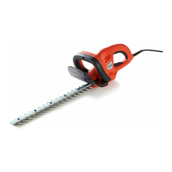
HT-52/ HT-48/ HT-42
Hedge Trimmers 520mm/ 480mm/ 420mm
Current (A)
Cycle (Hz)
1.9
50/60
1.8
50/60
1.8
50/60
Model No.
HT-52
520
(20-1/2)
=spm*
1
1
3.0
(6.6)
HT-52
Model No.
Length (L)
921 (36-1/4)
Width (W)
Height (H)
Continuous Rating (W)
Input
400
400
400
HT-48
HT-42
480
420
(18-7/8)
(16-1/2)
1,600
18
(11/16)
Double insulation
0.3 (0.98)*
2
2.9
2.8
(6.4)
(6.1)
PRODUCT
W
L
Dimensions: mm (")
HT-48
871 (34-1/4) 821 (32-1/4)
194 (7-5/8)
194 (7-5/8)
Max. Output (W)
Output
---
---
---
---
---
---
P 1/ 5
H
HT-42
Advertisement

Related Manuals for Dolmar HT-52


Summary of Contents for Dolmar HT-52
- Page 1 ECHNICAL INFORMATION PRODUCT P 1/ 5 Model No. HT-52/ HT-48/ HT-42 Description Hedge Trimmers 520mm/ 480mm/ 420mm ONCEPT AND MAIN APPLICATIONS These three Hedge trimmers have been developed for do-it-yourselfers, featuring compact, lightweight and more improved handling. Dimensions: mm (")
-
Page 2: Necessary Repairing Tools
P 2/ 5 epair CAUTION: 1) Unplug the machine for safety before repair/ maintenance ! 2) Do not touch the shear blades of Blade complete ! [1] NECESSARY REPAIRING TOOLS Code No. Description Use for 1R034 Bearing setting plate 12.2 Removing Gear 1R269 Bearing extractor Removing Bearing box complete... - Page 3 P 3/ 5 epair [3] DISASSEMBLY/ASSEMBLY [3] -1. Blade complete and Front handle (cont.) ASSEMBLING Take the disassembling step in reverse. Note: Be sure to set Flat washer 8 and two Spindle sleeves in place. (Figs. 7 and 8) Align the convex of Switch lever B with the depressions of L/R Housing set on the vertical lines, (Fig. 9) and then fit their convex into their protrusions by enlarging Front grip portion carefully and shifting it.
- Page 4 P 4/ 5 epair [3] DISASSEMBLY/ASSEMBLY [3] -3. Armature, Switch and Power supply cord DISASSEMBLING 1) Remove Blade complete and Gear. (Refer to pervious pages.) Carbon brushes, Switch and Power supply cord can be removed. 2) Remove Rod whose ends are linked to Switch lever A and Switch arm B. Conseqently, Switch lever A with Spring, Switch arm B and Switch lever Fig.
-
Page 5: Circuit Diagram
P 5/ 5 epair [3] DISASSEMBLY/ASSEMBLY [3] -4. Switch lever B (and Front handle) DISASSEMBLING Fig. 19 Refer to the clause of [3]-1. protrusion of tab of Switch Switch lever B lever B ASSEMBLING protrusion of Front handle 1) When separating Front handle from Switch lever B; - hook one end of Spring with the protrusion of Front handle.
Need help?
Do you have a question about the HT-52 and is the answer not in the manual?
Questions and answers