Table of Contents
Advertisement
PARTS & ACCESSORIES
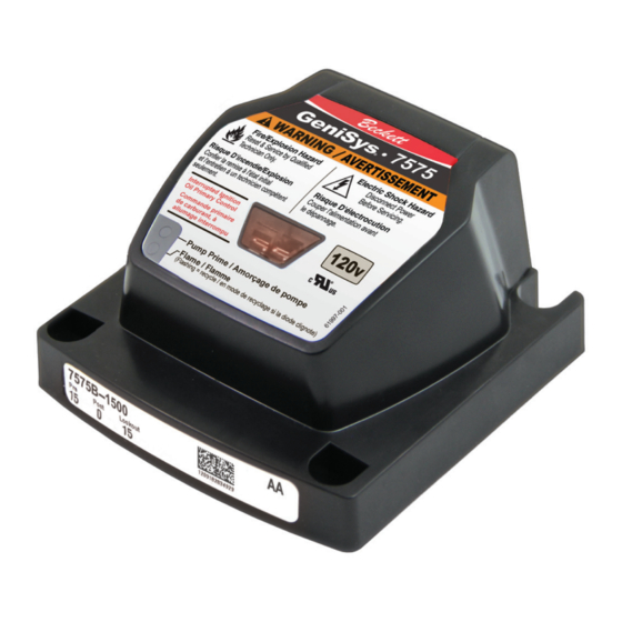
GeniSys
Model 7575
Advanced Burner Control
CLICK ANYWHERE on THIS PAGE to RETURN to
BECKETT BURNERS & CONTROLS at
InspectApedia.com
Description / Applications
The Beckett GeniSys
120 Vac primary safety control for residential and light
commercial oil burners used in boiler, furnace, and
water heater applications having firing rates less than 20
GPH. The GeniSys is used with a suitable cad cell flame
sensor to control the oil burner motor, igniter, and optional
solenoid valve. It has 24 Vac thermostat terminals
compatible with both mechanical and many power stealing
thermostats. It can also provide interrupted or intermittent
duty ignition.
120V
®
Advanced Burner Control is a
®
Advertisement
Table of Contents

Related Manuals for Beckett GeniSys 7575


Summary of Contents for Beckett GeniSys 7575
- Page 1 120V ® Model 7575 PARTS & ACCESSORIES Advanced Burner Control CLICK ANYWHERE on THIS PAGE to RETURN to BECKETT BURNERS & CONTROLS at InspectApedia.com Description / Applications The Beckett GeniSys Advanced Burner Control is a ® 120 Vac primary safety control for residential and light...
-
Page 2: Table Of Contents
Contents Features................3 Electrical Ratings ..............5 Environmental Ratings: ............5 Installation/Operation/Maintenance .......5 Mounting: ................6 Wiring: ..................6 Typical Wiring: ................ 7 Startup / Checkout ............8 Starting the System..............8 Check Safety Features ............8 Sequence of Operation ...........9 Burner States ................. 9 Reset Button Operation ............ -
Page 3: Features
◦ Welded Relay Protection ◦ Limited Recycle ◦ Limited Reset ◦ 3 Status Lights ◦ Valve-On Delay / Motor-Off Delay (Field programmable with Beckett Contractor Tool) ◦ 15 Second Lockout Time ◦ Interrupted or Intermittent Duty Ignition ◦ Technician Pump Priming Mode ◦... - Page 4 Figure 1 – Getting to know the control Reset Button with Red Light Yellow Light Green Light Wiring Connections Communication Port Cad Cell Connections Thermostat Terminals...
-
Page 5: Electrical Ratings
Installation/Operation/ Do Not Use This Maintenance Control in an Application that is Not Within the Ratings Listed in This Professional Section. Improper Control Operation Service Required May Result. Incorrect installation or misuse of this control could result in Electrical Ratings severe personal injury, death, or substantial property damage from Inputs:... -
Page 6: Mounting
Incorrect Wiring Fire or Explosion Will Result in Hazard Improper Control Operation Can cause severe injury, death, or • GeniSys wiring label colors may not match property damage. the wire colors of the burner or other manufacturers’ controls. • Avoid prolonged exposure to water •... -
Page 7: Typical Wiring
Typical Wiring: Figure 2 – 7575A Interrupted ignition, no valve-on or motor-off delay ► IGNITER IGNITER L2 (IGN) MOTOR GeniSys MOTOR Control L2 (MTR) SAFETY AND LIMIT OPERATING LIMITS LIMIT JUMPER/ VALVE THERMOSTAT L2 (VLV) CAD CELL Figure 3 – 7575P Interrupted ignition, valve-on and motor-off delays ►... -
Page 8: Startup / Checkout
Startup / Checkout that the control remains in Standby mode. Fire Hazard 4. End the call for heat and remove the Reset and Service by Qualified cad cell jumper. Technician only. ◦ Simulate Flame Failure and Ignition Failure If the burner or control fails any of the 1. -
Page 9: Sequence Of Operation
Sequence of Operation Burner States Pump Standby prime 1. Standby: The burner is idle, waiting for a call for heat. Trial for Valve-on Lockout ignition delay 2. Valve-On Delay: The igniter and motor are on while the control Ignition delays turning on the oil solenoid carryover valve for the programmed time. -
Page 10: Priming The Pump
2. Initiate a call for heat. Priming the Pump 3. After the burner starts, press and 1. Prepare the burner for priming hold the reset button for 15 seconds by attaching a clear plastic hose until the yellow light turns on. This over the bleed port fitting and fully indicates that the button has been opening the pump bleed port. -
Page 11: Cad Cell Resistance Measurement
Any time the burner is running, press Cad Cell Resistance Measurement and hold the reset button to disable the The Beckett 7575 control cad cell burner. The burner will remain off as resistance can be selected and read long as the button is held. -
Page 12: Limited Warranty Information
1. Visit our website at: www.beckettcorp.com/warranty 2. Email your request to: rwb-customer-service@beckettcorp.com 3. Write to: R. W. Beckett Corporation, P. O. Box 1289, Elyria, OH 44036 NOTE: Beckett is not responsible for any labor cost for removal and replacement of equipment.
Need help?
Do you have a question about the GeniSys 7575 and is the answer not in the manual?
Questions and answers