Advertisement
Quick Links
IMPORTANT SAFETY INSTRUCTIONS
Read all safety warnings, instructions,
WARNING
ed with this accessory, as well as those provided with
your power tool, battery pack, and charger. Failure to
or serious injury. Save all warnings and instructions for
future reference. READ ALL SAFETY INSTRUC-
TIONS BEFORE USE.
WARNING
Always wear eye protection.
To change the string trimmer head assembly:
1. Remove the battery pack.
Insert the pin supplied with Easy Load Trimmer
2.
Head replacement into gearcase hole (Fig 1) .
NOTE: Do NOT remove the pin until new trimmer
head is installed.
3.
Slowly rotate head anticlockwise until pin drops into
gear detent, locking the gear in place. Rotate the
trimmer head anticlockwise and remove from
spindle (Fig 2).
4. Thread the new trimmer head onto the spindle and
rotate clockwise. Hand-tighten securely.
Do not use blades, brush cutting
WARNING
wheels, accessories, or attachment
other than those recommended by MILWAUKEE
Serious injury or product damage may occur.
When replacing the line, for best performance use
2.0 mm (0.080") or 2.4 mm (0.095") diameter line. The
trimmer head also supports line diameters of
2.7 mm (0.105") and 2.9 mm (0.115").
Installing the Cutting Line
Use
only
MILWAUKEE
Specifications). Replace the cutting line with either
6.1 m (20') of 2.4 mm (0.095") line or 7.6 m (25') of
2.0 mm (0.080") line.
NOTE: When used near abrasive surfaces or in dense
growth, the cutting line will wear faster.
1. Remove the battery pack.
2. Clean any grass or debris from the trimmer head.
3.
Measure out 6.1 m (20') of 2.4 mm (0.095") line or
7.6 m (25') of 2.0 mm (0.080") line.
When replacing the line, use only
CAUTION
MILWAUKEE
(0.080" or 0.095") diameter line. Any other line can
degrade performance or cause damage to the
trimmer.
4.
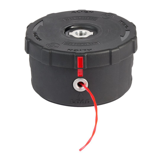
Rotate the housing plate to align the red indicators
on the housing plate with the red indicators above
the eyelets (Fig 3).
5.
Insert the line through either eyelet and push through
the head so an equal amount of line extends from
each eyelet.
1
Fig. 1
2
3
EASY LOAD TRIMMER HEAD
Cat. No.: 49162748
trimmer
line
®
2.0 mm or 2.4 mm
®
1
Fig. 2
2
3
Begin winding the line by rotating the housing plate
6.
in the direction of the arrows. Continue twisting until
100 mm to 150 mm of line extends from the eyelets
-
(Fig 4).
7. Check that the exposed line extends no further than
the line blade. If the exposed line is too long, continue
winding the housing plate or trim before use (Fig 5).
NOTE: Under normal operation, the remaining string
should be thrown from the spinning head during use.
8.
Replace the housing cover by aligning the clips with
the retaining apertures and press the housing until
the tabs click into place.
Replacing the Cutting Line
If any line remains in the head that needs to be discard-
ed, or a new line is to be used, the housing cover can
be removed and the existing line replaced.
1. Remove the battery pack.
2.
Turn trimmer head over and press the two release
tabs on either side of the head.
3. Remove the trimmer head housing cover.
4. Remove any existing line.
5. Replace the trimmer head housing cover by aligning
the retaining tabs with the corresponding apertures
and press the housing into place until the tabs click
into place.
NOTE: Ensure the housing cover appears level and
firmly fixed in place. If it appears tilted to one side,
.
®
remove the housing cover and repeat the step
above
6. Install new line as directed in the Installing the
Cutting Line section.
Store extra line in a sealed plastic bag with a tablespoon
(see
of water to avoid drying or cracking. Periodically sharpen
the line cutter to ensure the line does not extend too long
from the spool, which can cause motor overload.
49162712...................... 2.0 mm x 4.5 m Trimmer Line
49162713 ...................... 2.4 mm x 7.6 m Trimmer Line
Fig. 3
Maintaining Line
SPECIFICATIONS
Fig. 4
Fig. 5
Advertisement

Related Manuals for Milwaukee 49162748


Summary of Contents for Milwaukee 49162748
- Page 1 NOTE: Ensure the housing cover appears level and firmly fixed in place. If it appears tilted to one side, other than those recommended by MILWAUKEE ® remove the housing cover and repeat the step Serious injury or product damage may occur.
- Page 2 Australia and New Zealand. SERVICE - AUSTRALIA and NEW ZEALAND MILWAUKEE ® prides itself in producing a premium quality product that is Nothing But Heavy Duty Your satisfaction with our products is very important to us! If you encounter any problems with the operation of this tool, please contact your authorised MILWAUKEE ®...
Need help?
Do you have a question about the 49162748 and is the answer not in the manual?
Questions and answers