Download Print this page
Sony ECM-44BMP Service Manual

Sony ECM-44BMP Service Manual

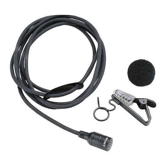
Electret condenser microphone
Hide thumbs Also See for ECM-44BMP:

Advertisement

ECM-77LM 
ECM-77BC 
ECM-77B
- For the ECM-77LM, refer to "Appendix (ECM-77LM)". 
- For the ECM-77BC, refer to "Appendix (ECM-77BC)". 
- For the ECM-77B, refer to "Appendix (ECM-77B)".
ELECTRET CONDENSER MICROPHONE
ECM-44BMP
ECM-77BMP
ECM-166BMP
SERVICE MANUAL
1st Edition (Revised 1)
Corrected on January 5, 2021

Advertisement

loading

Summary of Contents for Sony ECM-44BMP

  • Page 1 ELECTRET CONDENSER MICROPHONE ECM-44BMP ECM-77BMP ECM-77LM  ECM-166BMP ECM-77BC  ECM-77B SERVICE MANUAL 1st Edition (Revised 1) - For the ECM-77LM, refer to "Appendix (ECM-77LM)".  - For the ECM-77BC, refer to "Appendix (ECM-77BC)".  - For the ECM-77B, refer to "Appendix (ECM-77B)". Corrected on January 5, 2021...
  • Page 2: Table Of Contents

    Refer all servicing to qualified service personnel. The material contained in this manual consists of information that is the property of Sony Corporation and is intended solely for use by the purchasers of the equipment described in this manual.
  • Page 3: Operation

    Electret Condenser Microphone is designed for use with a transmitter having a 3-pole minijack with a lock mechanism used in a Sony 800-MHz band wireless microphone system. Connecting to the Transmitter (See fig. A.) Connect the output connector of the microphone to the input connector of the transmitter.
  • Page 4: Ecm-44Bmp

    ECM-44BMP 2. ECM-44BMP 2-1. SCHEMATIC DIAGRAM AMPLIFIER CABLE CASE ASSY 3-pole mini Phone plug Chip Ring CAPSULE Sleeve SHIELD 2-2. SPARE PARTS Part No. SP Description A-4510-056-A s CAPSULE ASSY A-8315-472-A s CASE ASSY, AMPLIFIER 1-500-249-21 s BEAD, FERRITE (CASE) (For CE model only) 2-3.
  • Page 5: Ecm-77Bmp

    1-500-249-21 s BEAD, FERRITE (CASE) (For CE model only) 3-4. ACCESSORIES SUPPLIED WIND SCREEN ASSY HORIZONTAL CLIP ASSY Q'ty Part No. SP Description X-5237-404-1 s SCREEN ASSY, WIND X-5237-410-1 s CLIP ASSY, HOLDER, HORIZONTAL 3-860-338-04 s MANUAL, INSTRUCTION ECM-44BMP ECM-77BMP ECM-166BMP...
  • Page 6: Ecm-166Bmp

    (For CE model only) Case (Bushing) Microphone Cable 4-4. ACCESSORIES SUPPLIED Built-in Microphone Index Part No. SP Description Unsolder. X-2536-801-1 s CLIP, ASSY, HOLDER 2-539-598-01 s SCREW, WINDOW — 3-860-338-04 s MANUAL, INSTRUCTION White Ground Source Built-in Microphone Drain ECM-44BMP ECM-77BMP ECM-166BMP...
  • Page 7: Appendix (Ecm-77Lm)

    Appendix (ECM-77LM) [Description] The connector of A-2207-775-A “CASE ASSY (S), AMPLIFIER” cannot be disassembled for servicing or replaced either. [Parts Registration Info.] CASE ASSY (S), AMPLIFIER A-2207-775-A Only for ECM-77LM (New) CAPSULE ASSY A-1541-734-A Common for ECM-77 (Existing part) CLIP ASSY, HORIZONTAL X-2537-404-6 Common for ECM-77 (Existing part) HOLDER...
  • Page 8 [Procedure] 1. Remove CAPSULE ASSY CAPSULE ASSY can be removed as shown in Fig.3. CASE ASSY(S),AMPRIFIE CAPSULE ASSY Screw locking Fig.3 compound 2. Install CAPSULE ASSY CAPSULE ASSY is installed as shown in Fig.4. CAPSUL Tightening torque::0.11 - 0.12Nm E ASSY Clean contact spring with ethanol.
  • Page 9 (2) Noise check (Bending test) Portion: Capsule side (Fig.6), Connector side (Fig.7) Operation: Take the cable while holding Capsule(connector), and bend it from right side to left side with an angle of 90 degrees by 2 - 3 times. Standard: Sound does not cut out and sound noise does not occur. 2–3time 2–3time Fig.6...
  • Page 10: Appendix (Ecm-77Bc)

    Appendix (ECM-77BC) [Corrections] The specifications of the ECM-77BC differ depending on whether it is improved one against the high frequency interference (supporting Digital WL) or not. The specifications can be recognized by the color of the microphone bushing. Microphone bushing: black = Not improved one Microphone bushing: gray (short) = improved one against the high frequency interference (1)
  • Page 11 A. Not improved unit for high frequency interference (bushing: black) 1. Schematic diagram AMPLIFIER CASE ASSY CABLE WHITE CAPSULE SHIELD Fig. 5 2. Part Required ⑤ ② ④ ⑨ ③ Fig. 6 ⑧ ⑦ ① Part Name Part No. Remarks Capsule ASSY A-1541-734-A Amplifier Case ASSY...
  • Page 12 3. Procedure 3-1. Wiring to the connector Connect the wore of the AMPLIFIER CASE ASSY to the CONNECTOR (PLUG). (Fig. 7) Notch Shield wire Red lead Shield wire White lead Fig. 7 3-2. Attaching the microphone bushing Apply the adhesive agent (Locktite (Prism 403) or equivalent) between the edge of the coating of the microphone cable and the point about 10mm from the edge (Fig.
  • Page 13 3-4. Attaching the connector cover 1) Applying the locking agent for screw Apply the locking agent for screw (ThreeBond 1401B:7-432-114-11 or equivalent) as indicated by the blue dot in Fig. 12 and attache the connector cover. Position to apply: 2 teeth of the screw of connector (with 5mm of width) Connector cover Fig.
  • Page 14 B. Improved unit for high frequency interference (1) (Bushing: Gray) 1. Schematic diagram AMPLIFIER CASE ASSY CABLE WHITE CAPSULE SHIELD Fig. 17 2. Part Required ⑩ ⑥ ⑤ ② ④ ④ ⑨ ③ Fig. 18 ⑧ ⑦ ① ■Improved unit for high frequency interference (1) (Bushing: gray) Part Name Part No.
  • Page 15 3. Procedure 3-1. Wiring to the connector 1) Attaching the jumper wire Connect between #2pin and #4pin by jumper wire. Reuse the jumper wire which is used originally. (Do not solder it at this moment.) (Fig. 19) Jumper wire Ground ring Fig.
  • Page 16 3-2. Attaching the microphone bushing Apply the adhesive agent (Locktite (Prism 403) or equivalent) between the edge of the coating of the microphone cable and the point about 10mm from the edge (Fig. 25), and the side of the heat shrinkable tube (Fig.
  • Page 17 3) Fixing the connector cover Apply thelocking agent for screw (ThreeBond 1401B:7-432-114-11 or equivalent) to the screw hole on the connector cover and tighten the supplied screw (tightening torque: 0.08Nm)(Fig. 31) Supplied screw Position to apply Connector cover Fig. 31 3-5.
  • Page 18 C. Improved unit for high frequency interference (2)(Bushing: Gray and long type) 1. Schematic diagram AMPLIFIER CASE ASSY CABLE WHITE CAPSULE SHIELD Fig. 35 2. Part Required ⑩ ⑥ ④ ② ④ ⑨ ③ Fig. 36 ⑧ ① ⑦ Part Name Part No.
  • Page 19 3. Procedure The procedure is the same as “B. Improved unit for high frequency interference (1)” other than “3-2. Attaching the microphone bushing” and “3-3. Attaching the cord clamp”. 3-2. Attaching the microphone bushing Apply the adhesive agent (Locktite (Prism 403) or equivalent) between the edge of the coating of the microphone cable and the point about 30-35 mm from the edge (Fig.
  • Page 20: Appendix (Ecm-77B)

    Appendix (ECM-77B) [Applicable S/No. ] Choice the parts according to below serial number. : #902000 or before : #902001 and after [Parts change info. And Applicable S/No. ] < Change point > - SLEEVE ASSY (Length and part number) - TRANSFORMER MOUNTED PWB (Mounted parts and part number) - No function and performance has changed.
  • Page 21 Fig.1 [How to identify] SLEEVE ASSY Length is different. 133mm : 133mm : 126mm Old : A-1908-370-C New : A-4531-042-C 126mm MOUNTED PWB, TRANSFORMER Mounted parts and board length are different. Fig.2 Capacitor Length Exist 38mm None 29mm Fig.4 Fig.3 Capacitor New (A-4538-027-B) New (A-4538-027-B)
  • Page 22 [Propcedure] 1. Remove the POWER BUSHING , Cable and EX-1251. 1-1. Remove the BATTERY SLEEVE. (Fig.5) 1-2. Press the protrusion both side and remove CASE LID. (fig.5) SPRING EX-1251 LID, CASE Cable Protrusion CASE, BATTERY Protrusion POWER BUSHING SLEEVE, BATTERY Fig.5 Fig.6 1-3.
  • Page 23 3. Assemble the CANNON PIN INSERT and TRANSFORMER MOUNTED PWB 3-1. Solder the wire (orange) which is from BATTERY CASE the land of TRANSFORMER MOUNTED PWB which is indicated red circle. (Fig.9) 3-2. Pass the three wires (red, purple (gray) and orange) through the hole of BATTERY CASE which is indicated blue circle and insert these wires to the grove between TRANSFORMER MOUNTED PWB and BATTERY CASE.
  • Page 24 3-4. Solder the wires (Purple(gray), Black and Green) to CANON PIN INSERT. (Fig.13) Wiring: Pin1 = Purple(gray) Pin2 = Green Pin3 = Black CANON PIN INSERT Black Purple (Gray) Green CANNON PIN SLEEVE Fig.13 3-5. Rotate the CANON PIN INSERT 4 to 6 times and insert to CANNON PIN SLEEVE. And fix it by screw which is bundled with CANON PIN INSERT.
  • Page 25 4-3. Wiring the Cable to PCB EX-1251 following way as Fig.18. Braided wire SPRING White Orange EX-1251 Purple Fig.18 4-4. Pass the wires that from TRANSFORMER MOUNTED PWB through to notch of EX-1251. Then insert the EX-1251 and SPRING to BATTERY CASE. (Fig.19) 4-5.
  • Page 26 4-7. Install the battery sleeve. (Fig.22) Case lid Battery case Battery case Battery Sleeve Fig.22 Fig.21 5. Operation Confirmation Equipment Required Audio Mixer AC-148F or the equivalent (For DC +48Vsupplying) Headphone 5-1. Connection Insert the AA batteries to ECM-77B and connect the audio cable to Audio mixer or power equipment.(Fig.23) To Audio Input connector Audio Mixer...
  • Page 27 5-2. Checking the audio output [Procedure] 1. Turn off the +48V power. 2. Speak to microphone. 3. Check that sound is normally output from the headphone. There shall be no perceptible distortion in the sound. There shall be no perceptible noise in the sound. The sound volume shall be appropriate.
  • Page 28 [Wiring] #870760 or before TRANSFORMER MOUNTED PWB Fig.26 #870761 to #902000 Fig.27...
  • Page 29 #902001 and after TRANSFORMER MOUNTED PWB Fig.28 [Circuit diagram] #870760 or before Fig.29...
  • Page 30 #870761 to #902000 Fig.30 #902001 and after Fig.31...
  • Page 32 ECM-44BMP (SY, CE) Printed in Japan ECM-77BMP (UC, CE) Sony Corporation 1998. 7 05 ECM-166BMP (UC, CE) J,E V1.01A 9-976-843-02 Broadcasting & Professional Systems Company ©1998...

This manual is also suitable for:

Ecm-77bmpEcm-166bmpEcm-77lmEcm-77bcEcm-77b