Sony ECM-DS70P Service Manual
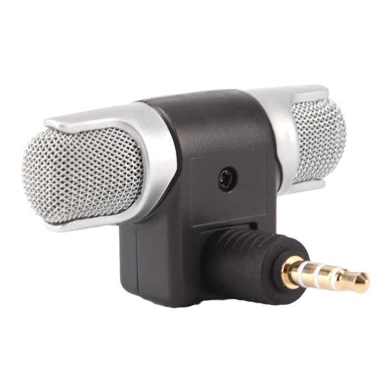
Electret condenser stereo microphone
Hide thumbs
Also See for ECM-DS70P:
- Operating instructions manual (6 pages) ,
- Specifications (6 pages) ,
- Operating instructions (4 pages)
Advertisement
Quick Links
Advertisement

Related Manuals for Sony ECM-DS70P


Summary of Contents for Sony ECM-DS70P
- Page 1 ECM-DS70P SERVICE MANUAL US Model Canadian Model Ver 1.1 2001. 03 AEP Model With SUPPLEMENT-1 E Model (9-923-256-81) SPECIFICATIONS ELECTRET CONDENSER STEREO MICROPHONE Sony Corporation 9-923-256-12 Audio Entertainment Group 2001C0200-1 General Engineering Dept. © 2001.3...
- Page 2 ECM-DS70P SECTION 1 DIAGRAM [PRINTED WIRING BOARD] [AMP BOARD] 1-667-840- MIC 1 MIC 2 MIC OUTPUT Note on Printed Wiring Boards: Note: • X : parts extracted from the component side. • b : Pattern on the side which is seen.
-
Page 3: Section 2 Exploded View
SECTION 2 EXPLODED VIEW NOTE : • -XX, -X mean standardized parts, so they • The mechanical parts with no reference may have some difference from the original number in the exploded views are not one. supplied. • Items marked “ * ”are not stocked since they are seldom required for routine service. -
Page 4: Electrical Parts List
ECM-DS70P SECTION 3 ELECTRICAL PARTS LIST NOTE : • Due to standardization, replacements in the • CAPACITORS When indicating parts by reference num- uF : µ F parts list may be different from the parts ber, please include the board. - Page 5 ECM-DS70P US Model Canadian Model SERVICE MANUAL AEPModel E Model 2001.03 SUPPLEMENT - 1 File this Supplement with the Service Manual. Subject : ADDITION OF ACCESORIES (US MODEL ONLY) Added follwing Accesories (Service Manual See page 4) Ref. No. Part No.
-
Page 6: Revision History
ECM-DS70P REVISION HISTORY Clicking the version allows you to jump to the revised page. Also, clicking the version at the upper right on the revised page allows you to jump to the next revised page. Ver. Date Description of Revision 2001.03...
Need help?
Do you have a question about the ECM-DS70P and is the answer not in the manual?
Questions and answers