Advertisement
Advertisement
Table of Contents

Related Manuals for Lifeline LLFWB


Summary of Contents for Lifeline LLFWB
- Page 1 OWNER’S MANUAL Tools Required: Adjustable Wrench Retain This Manual For Reference Escalade Sports PO Box 889 Evansville, IN 47706 www.lifelinefitness.com tel: 888.467.4485 fax: 312.279.0601 Please contact Customer Service with any questions: 888.467.4485 or service@lifelinefitness.com 2L-7644-00...
-
Page 2: Table Of Contents
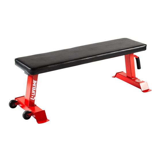
TABLE OF CONTENTS BEFORE YOU BEGIN..................……….. 1 IMPORTANT SAFETY NOTICES..............……….. 2 WARNING LABEL PLACEMENT………………………………………………………….. 3 HARDWARE PACK..…..............……………….. 4 ASSEMBLY INSTRUCTIONS.................……….. 5 EXPLODED DIAGRAM………………………………………………………………..…….7 PARTS LIST………………………………………………………………………………..8 BEFORE YOU BEGIN Thank you for selecting the Flat Weight Bench. For your safety and benefit, read this manual carefully before using the machine. -
Page 3: Important Safety Notices
IMPORTANT SAFETY NOTICE PRECAUTIONS Certain precautions apply when you operate a piece of exercise equipment. Be sure to read the entire manual before you assemble or operate your machine. In particular, note the following safety precautions: 1. Keep children and pets away from the machine at all times. DO NOT leave children unattended in the same room with the machine. -
Page 4: Warning Label Placement
WARNING LABEL PLACEMENT The warning labels shown here have been placed on Base Frame... -
Page 5: Hardware Pack
HARDWARE PACK NOTE: The following parts are not drawn to scale. Please use your own ruler to measure the size. : : : M8*20 M10*65 M8*95 : : : 8/16mm 10/20mm M8mm... -
Page 6: Assembly Instructions
ASSEMBLY INSTRUCTION Tools Required for Assembling the Machine: Adjustable Wrench and Allen Wrench. It is strongly recommended that this machine be assembled and moved by two or more people to avoid possible injury. Always hand tighten Nuts and Bolts first and do not tighten all Nuts and Bolts until instructed to do so. STEP 1 (See Diagram 1) A.) Attach Front Base Tube (1) to Main Frame (3) using two Hex Head Bolts (10) and two Washers (15). - Page 7 STEP 2 (See Diagram 2) A.) Attach the Seat Pad (4) to the Main Frame (3) using four L Shaped Brackets (5) and four Hex Head Bolts (13), eight Washers (16), two Hex Head Bolts (11) and two Nuts (14). B.) Securely tighten all Nuts and Bolts.
-
Page 8: Exploded Diagram
EXPLODED DIAGRAM... -
Page 9: Parts List
PARTS LIST PART Description Remark Front Base Tube (With wheels) Rear Base Tube (Without wheels) Main Frame Seat Pad L Shaped Bracket Wheel Pre-assembled Foam Grip Pre-assembled End Cap (76.5x50.8mm) Pre-assembled End Cap(φ25mm) Pre-assembled Hex Head Bolt M10*65 Hex Head Bolt M8*95 Hex Head Bolt M8*45 Pre-assembled Hex Head Bolt M8*20...
Need help?
Do you have a question about the LLFWB and is the answer not in the manual?
Questions and answers