Advertisement
Quick Links
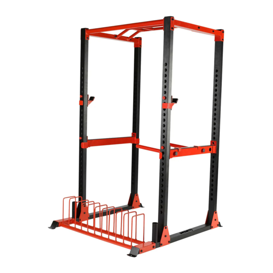
OWNER'S MANUAL
Tools Required:
14-17mm Box wrench
Retain This Manual For Reference
Escalade Sports
PO Box 889
Evansville, IN 47706
www.lifelinefitness.com
tel: 888.467.4485
fax: 312.279.0601
Please contact Customer Service with any questions: 888.467.4485 or service@lifelinefitness.com
2L-7645-00
CPSIA#2-LLPRC1-CA-0419
Advertisement

Subscribe to Our Youtube Channel
Related Manuals for Lifeline PRO POWER RACK C1


Summary of Contents for Lifeline PRO POWER RACK C1
- Page 1 OWNER’S MANUAL Tools Required: 14-17mm Box wrench Retain This Manual For Reference Escalade Sports PO Box 889 Evansville, IN 47706 www.lifelinefitness.com tel: 888.467.4485 fax: 312.279.0601 Please contact Customer Service with any questions: 888.467.4485 or service@lifelinefitness.com 2L-7645-00 CPSIA#2-LLPRC1-CA-0419...
-
Page 2: Table Of Contents
TABLE OF CONTENTS BEFORE YOU BEGIN..................…………1 IMPORTANT SAFETY NOTICES..............…………2 WARNING LABEL PLACEMENT…………………………………………………………..4 HARDWARE PACK..…..............…………………5 ASSEMBLY INSTRUCTIONS.................…………6 EXPLODED DIAGRAM……………………………………….……………………………. 9 PARTS LIST……………………………………………………………………………..…. 10 BEFORE YOU BEGIN Thank you for selecting the Pro Power Rack. For your safety and benefit, read this manual carefully before using the machine. -
Page 3: Important Safety Notices
IMPORTANT SAFETY NOTICE PRECAUTIONS Certain precautions apply when you operate a piece of exercise equipment. Be sure to read the entire manual before you assemble or operate your machine. In particular, note the following safety precautions: 1. Keep children and pets away from the machine at all times. DO NOT leave children unattended in the same room with the machine. - Page 4 CARE AND MAINTENANCE 1. Periodically lubricate moving parts with WD-40 or light oil. 2. Inspect and tighten all parts before using the machine. DO NOT overtighten. If parts are worn or damaged, DO NOT use. 3. Failure to examine regularly may affect the safety level of the machine. 4.
-
Page 5: Warning Label Placement
WARNING LABEL PLACEMENT The warning labels shown here have been placed on the Base Frame. -
Page 6: Hardware Pack
HARDWARE PACK... -
Page 7: Assembly Instructions
ASSEMBLY INSTRUCTION A flat area of 6’ x 6’ will be required to properly assemble the Full Rack. The following tools will be required to completed the assembly of the Full Rack: 14-17mm Box wrench All plastic end caps and plugs have been assembled on the unit prior to shipment. They are shown on the assembly drawing for reference in the event replacement parts are needed. - Page 8 Diagram 1. Main Frame Assembly Step 2 Check the assembly against illustrations and tighten all nuts and bolts securely.
- Page 9 Step 3 (See Diagram 3) a) Attach Bar Hooks (8 and 9) and Spotter Hooks (11 and12) onto the assembled frame per Diagram 3. b) Attach left and right Safety Spotters (10 and 13) to left and right Spotter Hooks (11 and12).
-
Page 10: Exploded Diagram
EXPLODED DIAGRAM... -
Page 11: Parts List
PARTS LIST Part # Description Remark Left/Right Base Frame Plate Storage Mainframe Upright Upper Front Cross Frame Monkey Bar Frame Support Plate Left/Right Upper Frame Right Bar Hook Left Bar Hook Left Safety Spotter Left Spotter Hook Right Spotter Hook Right Safety Spotter Left Dip-up Handle Right Dip-up Handle...
Need help?
Do you have a question about the PRO POWER RACK C1 and is the answer not in the manual?
Questions and answers