Advertisement
Quick Links
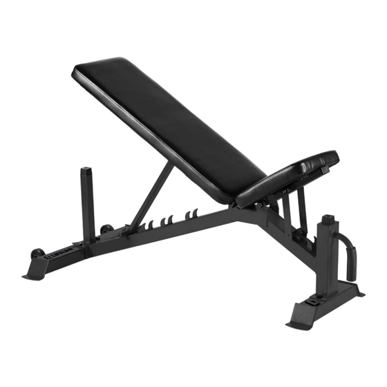
OWNER'S MANUAL
Tools Required:
Adjustable Wrench
Retain This Manual For Reference
Escalade Sports
PO Box 889
Evansville, IN 47706
www.lifelinefitness.com
tel: 888.467.4485
fax: 312.279.0601
Please contact Customer Service with any questions: 888.467.4485 or service@lifelinefitness.com
2L-7643-00
CPSIA#2-LLUWB-BLK-CA-0419
Advertisement

Subscribe to Our Youtube Channel
Related Manuals for Lifeline LLUWB-BLK


Summary of Contents for Lifeline LLUWB-BLK
- Page 1 OWNER’S MANUAL Tools Required: Adjustable Wrench Retain This Manual For Reference Escalade Sports PO Box 889 Evansville, IN 47706 www.lifelinefitness.com tel: 888.467.4485 fax: 312.279.0601 Please contact Customer Service with any questions: 888.467.4485 or service@lifelinefitness.com 2L-7643-00 CPSIA#2-LLUWB-BLK-CA-0419...
-
Page 2: Table Of Contents
TABLE OF CONTENTS BEFORE YOU BEGIN..................………... 1 IMPORTANT SAFETY NOTICES..............………... 2 WARNING LABEL PLACEMENT…………………………………………………………... 3 HARDWARE PACK..…..............…………………. 4 ASSEMBLY INSTRUCTIONS.................………... 5 EXPLODED DIAGRAM……………………………………………………………………….9 PARTS LIST…………………………………………………………………………………. .10 INCLINE ADJUSTMENT ……………………………… ……………………………...….11 BEFORE YOU BEGIN Thank you for selecting the Utility Weight Bench. For your safety and benefit, read this manual carefully before using the machine. -
Page 3: Important Safety Notices
IMPORTANT SAFETY NOTICE PRECAUTIONS Certain precautions apply when you operate a piece of exercise equipment. Be sure to read the entire manual before you assemble or operate your machine. In particular, note the following safety precautions: 1. Keep children and pets away from the machine at all times. DO NOT leave children unattended in the same room with the machine. -
Page 4: Warning Label Placement
WARNING LABEL PLACEMENT The warning labels shown here have been placed on the Main Frame & Front Base. -
Page 5: Hardware Pack
HARDWARE PACK NOTE: The following parts are not drawn to scale. Please use your own ruler to measure the size. -
Page 6: Assembly Instructions
ASSEMBLY INSTRUCTION It is strongly recommended that this machine be assembled and moved by two or more people to avoid possible injury. STEP 1 (See Diagram 1) A.) Attach Front Base Tube (1) and Rear Base Tube (2) to Main Frame (3) using four Hex Head Bolts (21), eight Washers (29) and four Nuts (26). - Page 7 STEP 2 (See Diagram 2) A.) Attach two Backrest Supports (4) to the Main Frame (3) using one Hex Head Bolts (18), two Washers (28) and one Nut (25). B.) Attach the Backrest Adjustable Support (5) to two Backrest Supports (4) using one Hex Head Bolts (18), two Washers (28) and one Nut (5).
- Page 8 STEP 3 (See Diagram 3) A.) Attach the Seat Support (7) to the Main Frame (3) using one Hex Head Bolt (20), two Washers (28) and one Nut (25). B.) Attach the Seat Adjustable Support (8) to Seat Support (7) using one Hex Head Bolt (19), two Washers (28) and one Nut (25).
- Page 9 STEP 4 (See Diagram 4) A.) Attach the Backrest (9) to Backrest Support (4) using four Hex Head Bolts (22) and four Nuts (30) B.) Attach Seat Pad (10) to Seat Support (7) using four Hex Head Bolts (24) and four Nuts (30).
-
Page 10: Exploded Diagram
EXPLODED DIAGRAM... -
Page 11: Parts List
PARTS LIST PART DESCRIPTION QUANTITY REMARK Front Base Tube Rear Base Tube Main Frame Backrest Support Backrest Adjustable Support Backrest Support Bracket Seat Support Seat Adjustable Support Bracket Seat Pad Wheel Pre-Assembled Pre-Assembled Rubber Bumper Foam Grip Pre-Assembled Square Inner Cap (50*25mm) Pre-Assembled Square Inner Cap (30*20mm) Pre-Assembled... -
Page 12: Incline Adjustment
INCLINE ADJUSTMENT When adjusting the Backrest Incline; make sure the Incline Support sits firmly onto the open slot on Main Frame to avoid possible injury.
Need help?
Do you have a question about the LLUWB-BLK and is the answer not in the manual?
Questions and answers