Table of Contents
Advertisement
Quick Links
INTRODUCTION
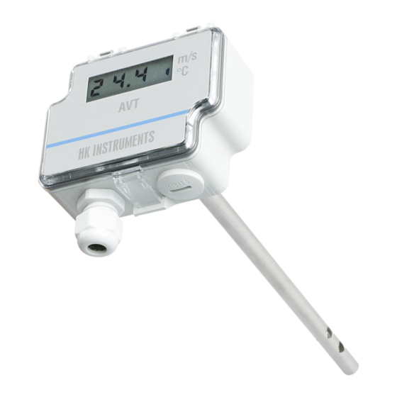
Thank you for choosing an HK Instruments AVT series air velocity
transmitter. The AVT series is intended for use in commercial environ-
ments. It is designed with a duct mount probe and adjustable collar
suitable for round or rectangular ducts. The AVT series provides sepa-
rate readings for air velocity and temperature.
The AVT series comes with three measurement ranges in a single de-
vice (0–2 m/s, 0–10 m/s, 0–20 m/s). The AVT series is available with
optional display and relay.
APPLICATIONS
AVT series devices are commonly used in HVAC/R systems for:
• in-duct air flow and velocity monitoring
• in-duct temperature monitoring
• VAV applications
SPECIFICATIONS
Performance
Measurement ranges:
Velocity:
Range: 0–2 m/s
Range: 0–10 m/s
Range: 0–20 m/s
Temperature: 0−50 °C
Accuracy:
Velocity:
Range: 0...2 m/s: <0.2 m/s + 5 % from reading
Range: 0...10 m/s: <0.5 m/s + 5 % from reading
Range: 0...20 m/s: <1.0 m/s + 5 % from reading
Thermal shift: ±0.8 % FS / °C
Units calibrated at 22 °C. Rapid thermal shift
stabilisation time 10 min.
Temperature: <0.5 ºC typical @25ºC (velocity > 0.5 m/s)
Technical Specifications
Media compatibility:
Dry air or non-aggressive gases
Measuring units:
m/s and °C
Measuring element:
Temperature: ntc10k
Velocity: Pt1000
Environment:
Operating temperature: 0...50 °C
Storage temperature: -20...70 °C
Humidity: 0 to 95 % rH, non-condensing
Copyright HK Instruments 2022
AIR FLOW AND VELOCITY TRANSMITTERS
AVT Series
• READ THESE INSTRUCTIONS CAREFULLY BEFORE ATTEMPTING
TO INSTALL, OPERATE OR SERVICE THIS DEVICE.
• Failure to observe safety information and comply with instructions
can result in PERSONAL INJURY, DEATH AND/OR PROPERTY
DAMAGE.
• To avoid electrical shock or damage to equipment, disconnect
power before installing or servicing and use only wiring with
insulation rated for full device operating voltage.
• To avoid potential fire and/or explosion do not use in potentially
flammable or explosive atmospheres.
• Retain these instructions for future reference.
• This product, when installed, will be part of an engineered system
whose specifications and performance characteristics are not
designed or controlled by HK Instruments. Review applications
and national and local codes to assure that the installation will
be functional and safe. Use only experienced and knowledgeable
technicians to install this device.
• Fuse at load supply (normally 6 A, 10 A, 16 A) does not always limit
the relay output load current to 6 A. Relay Maximum Load (250 V x
6 A res.)
• Add an external fuse to relay common connector. Use a time-lag
fuse (max 6 A) that is in accordance with the standard IEC 60127-2.
The product doesn't have an internal fuse for the relay.
CAUTION: The product may only be connected to overvoltage
category II electricity network according to IEC 60664-1.
Physical
Dimensions:
Case : 86.0 x 95.0 x 36.0 mm
Probe: OD 10 mm, length 210 mm from bottom of the
cover
Immersion Length with Flange: Adjustable 50–180 mm
Weight:
220 g
Mounting:
Mounting flange, ø 4.0 mm
Materials:
Case: ABS
Lid: PC
Probe: Stainless steel 304
Mounting flange: LLPDP
Protection standard:
IP54
Display
3 1/2 digit LCD backlit display
Size: 45.7 x 12.7 mm
Electrical connections:
Power supply & signal out: 4-screw terminal block
16–24 AWG (0.2–1.5 mm
Relay Out: 3-screw terminal block
16-24 AWG (0.2–1.5 mm
Cable entry:
M16
www.hkinstruments.fi
WARNING
Electrical
Input: 24 VDC / 24 VAC ± 10 %
Current consumption 35 mA (50 mA with relay)
+ 40 mA with mA-outs
Output signal 1: (T out)
0–10 V (linear to temperature)
4–20 mA (linear to temperature)
Output signal 2: (v out)
0–10 V (linear to m/s)
4–20 mA (linear to m/s)
Relay Out: 3-screw terminal block
Potential free SPDT
250 VAC, 6A / 30 VDC, 6 A adjustable switching point
and hysteresis
Conformance
Meets the requirements for:
)
2
EMC:
)
RoHS:
2
LVD/EESR:
WEEE:
INSTRUCTIONS
L min 1 kΩ
L max 400 Ω
L min 1 kΩ
L max 400 Ω
(NC, COM, NO)
CE:
UKCA:
2014/30/EU
S.I. 2016/1091
2011/65/EU
S.I. 2012/3032
2014/35/EU
S.I. 2016/1101
2012/19/EU
S.I. 2013/3113
RoHS
COMPLIANT
Installation version 7.0 2022
Advertisement
Table of Contents

Subscribe to Our Youtube Channel
Related Manuals for HK Instruments AVT Series


Summary of Contents for HK Instruments AVT Series
- Page 1 The AVT series comes with three measurement ranges in a single de- power before installing or servicing and use only wiring with vice (0–2 m/s, 0–10 m/s, 0–20 m/s). The AVT series is available with insulation rated for full device operating voltage.
- Page 2 Tighten the screw Figure 1c - Mounting orientation Air flow direction Air flow direction 36.0 15.0 15.0 Strain relief facing down Air flow direction Air flow direction Air flow direction 210.0 Copyright HK Instruments 2022 www.hkinstruments.fi Installation version 7.0 2022...
- Page 3 2) Select the desired measurement mode (see step 4). Velocity output (vout): v = voltage (V) 3) Configure the relay (optional) (see step 5). The device is now ready to be used. Copyright HK Instruments 2022 www.hkinstruments.fi Installation version 7.0 2022...
- Page 4 0,25 m/s. As the velocity increases over 1,5 m/s, the relay will open/close. As velocity reduces, the relay will not close/open until the velocity passes 1,25 m/s, thus preventing rapid cycling. Copyright HK Instruments 2022 www.hkinstruments.fi Installation version 7.0 2022...
Need help?
Do you have a question about the AVT Series and is the answer not in the manual?
Questions and answers