
Related Manuals for Airlocker RD212


Summary of Contents for Airlocker RD212
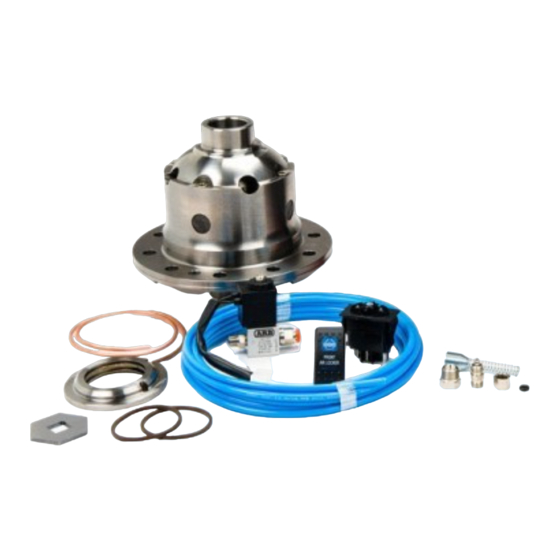
- Page 1 RD212 MITSUBISHI 9”, REAR, 28 SPLINE AIR OPERATED LOCKING DIFFERENTIAL INSTALLATION GUIDE...
- Page 2 No liability is assumed for damages resulting in the use of the information contained herein. ARB AIR LOCKER Locking Differentials and AIR LOCKER are trademarks of ARB Corporation Limited. Other product names used herein are for identification purposes only and may be trademarks of their respective owners. ARB 4x4 ACCESSORIES Corporate Head Office 42-44 Garden St...
-
Page 3: Table Of Contents
Table of Contents: 1 Introduction 1.1 Pre-Installation Preparation 1.2 Tool-Kit Recommendations 2 Removing the Existing Differential 2.1 Vehicle Support 2.2 Differential Fluid Drain 2.3 Removing the Axles and Differential 2.4 Marking the Bearing Caps 2.5 Checking the Current Backlash Amount 2.6 Removing the Differential Carrier 2.7 Use of the Thrust Block 3 Installing the Air Locker... -
Page 5: Introduction
1 Introduction IMPORTANT : BEFORE ATTEMPTING TO DISMANTLE YOUR VEHICLE FOR THIS INSTALLATION, PLEASE READ THIS INSTALLATION GUIDE IN ITS ENTIRETY, AS WELL AS ALL APPLICABLE SECTIONS OF YOUR VEHICLE MANUFACTURER’S SERVICE MANUAL. Pre-Installation Preparation This booklet is to be used in conjunction with your vehicle manufacturer’s service manual. -
Page 6: Tool-Kit Recommendations
1 Introduction Tool-Kit Recommendations Below is a list of tools and supplies you may need to complete this installation. Requirements for your vehicle may vary. Please consult your vehicle service manual for additional recommendations. Tools 1.2.1 Standard automotive sizes (metric and/or imperial) of sockets, wrenches, Allen keys, and drills. -
Page 7: Removing The Existing Differential
2 Removing the Existing Differential Vehicle Support Safely secure the vehicle on a hoist. We recommend supporting the vehicle on a chassis hoist to keep the differential area at a convenient working height and to leave the wheels and axles free to be rotated and removed. -
Page 8: Marking The Bearing Caps
2 Removing the Existing Differential Marking the Bearing Caps Using a small pointed center punch, gently mark the bearing caps in a way that will enable you to know which cap is ‘LEFT’ and which cap is ‘RIGHT’, which way is ‘UP’ and which way is ‘DOWN’. (Fig.1.) ... -
Page 9: Checking The Current Backlash Amount
2 Removing the Existing Differential Checking the Current Backlash Amount IMPORTANT: This step is a precautionary measure recommended by ARB due to the fact that some after market ring and pinion sets have been manufactured to run with different backlash settings than those specified by your vehicle manufacturer. -
Page 10: Removing The Differential Carrier
2 Removing the Existing Differential Removing the differential carrier Remove the adjuster nut locking tabs. Remove the bearing caps. Loosen the adjuster nuts. Carefully remove the differential carrier from the housing. Remove the tapered roller bearings from the differential carrier with a bearing puller. -
Page 11: Use Of The Thrust Block
2 Removing the Existing Differential Use of the Thrust Block This Air Locker has been designed to replace both drum and disc brake Mitsubishi diffs. As such, a thrust block used to maintain axle end float has been supplied for some drum brake equipped models. NOTE : Not all drum brake equipped models require use of a thrust block. -
Page 12: Installing The Air Locker
3 Installing the Air Locker Mounting the Ring Gear Remove the bolts that hold the ring gear in place. Using a soft mallet or copper hammer, tap in a circle around the ring gear to separate it from the differential carrier. ... - Page 13 3 Installing the Air Locker Figure 5.
-
Page 14: Installing The Carrier Bearings
3 Installing the Air Locker Installing the Carrier Bearings With the Air Locker well supported in an arbor press, apply a thin film of high pressure grease to both bearing journals. Identify the bearings according to where each was removed from the OE diff, and allocate them to the correct sides of the Air Locker respectively. -
Page 15: Drilling And Tapping The Bulkhead Port
3 Installing the Air Locker Drilling and Tapping the Bulkhead Port An air line port must be drilled and tapped through the differential housing to mount the bulkhead fitting into. Mark a spot on the seal housing side of the differential, on the flat between the third member mounting face and the bearing seat, as shown. -
Page 16: Final Air Locker Assembly
3 Installing the Air Locker Final Air Locker Assembly Clean all parts of the differential assembly making sure the O-ring grooves are free from any contaminants (e.g., dirt, water, metal fillings, etc.) Place the Air Locker into the differential housing and install the bearing caps. -
Page 17: Checking The Backlash
3 Installing the Air Locker Checking the Backlash Set a depth indicator on one of the ring gear teeth (Fig.8.). While supporting the pinion gear by holding the drive shaft flange, rotate the differential in both directions while observing the maximum variation in depth from the indicator (i.e., the highest value minus the lowest value). -
Page 18: Installing The Seal Housing
3 Installing the Air Locker Installing the Seal Housing Make sure the grooves and airway of the seal housing are clean and free from any contaminants (e.g. water, dirt, metal filings, etc.). Inspect the seal housing O-rings (supplied) for dirt, damage or other conditions which might cause leaks. - Page 19 3 Installing the Air Locker NOTE : The locking tab needs to be modified to suit the supplied adjuster nut and seal housing. Position the tab where it will be assembled, and re-determine the bending line for the end tip. ...
-
Page 20: Setting Up The Bulkhead Fitting
3 Installing the Air Locker Setting up the Bulkhead Fitting Apply thread sealant to the outside threads of the bulkhead body. Screw the bulkhead body into the tapped hole, and lightly tighten using a 14mm [9/16”] spanner. Wipe the area clean of any excess thread sealant (inside and outside of the housing). - Page 21 3 Installing the Air Locker Insert the free end of the seal housing tube into the bulkhead fitting until it protrudes approximately 8mm [5/16”] through the other side. From the outside of the housing, assemble one of the small O-rings over the top of the short length of seal housing tube protruding through the bulkhead fitting.
-
Page 22: Profiling The Seal Housing Tube
3 Installing the Air Locker Profiling the Seal Housing Tube With the seal housing tube now firmly secured into the bulkhead fitting, bend the tube so that it closely follows the profile shown in Fig.14. and 15. Check that the contour of the tube will not interfere with the bearing caps, the Air Locker or the seal housing front face. - Page 23 3 Installing the Air Locker IMPORTANT: In order for the seal housing to float and self center on the bearing journal, the seal housing tube must not be pulling against the seal housing. To check this, rotate the drive flange back and forth while observing the seal housing movement.
-
Page 24: Bench Testing The Air Locker
3 Installing the Air Locker Bench Testing the Air Locker To test the Air Locker, when 620kPa [90 PSI] shop air is applied to the seal housing tube, the Air Locker should engage. Check all fittings and the seal housing for air leaks. ... -
Page 25: Reinstalling The Differential & Axles
3 Installing the Air Locker Reinstalling Differential and Axles 3.10 Reinstall the third member to the differential housing according to your vehicle service manual. Reinstall the drive shaft. Replace the axle seals if necessary and fit to the axles. ... -
Page 26: Installing The Air System
4 Installing the Air System Mounting the Solenoid Connection to an ARB Air Compressor (Fig.17.) 4.1.1 Remove one of the 1/8” BSP plugs from its port in the compressor tank. Apply Teflon paste to the 1/8” BSP nipple on the solenoid and insert it into the port and tighten. - Page 27 4 Installing the Air System Connection to an Alternate Air Source 4.1.2 For ease of installation, quality of air supply, and a high level of dependability from your Air Locker(s), ARB strongly recommends use of a genuine ARB Air Compressor, however, the Air Locker air system can be operated on any alternate air source that meets each of the following guidelines: ...
-
Page 28: Running & Securing The Air Line
4 Installing the Air System Running and Securing the Air Line The path taken by the air line from your air source (i.e., compressor) to your Air Locker is unique to your vehicle and the position of your air source. Plan ahead carefully when running the air line and always follow these guidelines: ... -
Page 29: Connection To The Bulkhead Fitting
4 Installing the Air System NOTE : To remove the air line from the push-in fitting; push the air line as far into the fitting as possible and hold, push inward on the flange, and then pull the air line free of the fitting. - Page 30 4 Installing the Air System Push the airline into the compression fitting body and screw the outer nut down onto it. Using a 12mm spanner, tighten the outer nut onto the compression fitting body. NOTE : Some force is required to crush the ferrule, however the outer compression nut will tighten against a stop.
-
Page 31: Mounting & Connecting The Electrical System
5 Mounting & Connecting the Electrical System Mounting the Actuator Switch(es) Air Locker actuator switch(es) can be easily panel mounted inside the vehicle in a 21mm x 36.5mm [0.83” x 1.44”] rectangular cutout. NOTE : Only attach the cover plate to the face of the switch once the switch has been mounted and wired correctly as the cover plates are designed to be difficult to remove. -
Page 32: Wiring The Actuator System
5 Mounting & Connecting the Electrical System Wiring the Actuator System Connection to an ARB AIR COMPRESSOR 5.2.1 When wiring the Air Locker actuator switch(es) and solenoid(s) to an ARB Air Compressor, all connections can easily be set up directly from the supplied wiring loom. - Page 33 5 Mounting & Connecting the Electrical System SWITCH TERMINAL IDENTIFICATION Figure 21. Connection to an Alternate Air Source 5 .2.2 When connecting the actuation switch to an alternate air source, the switch(es) should be wired according to figures 22. and 23. depending on whether one or two Air Lockers will be installed in the vehicle.
- Page 34 5 Mounting & Connecting the Electrical System Dual Air Locker System 5.2.2.2 If two Air Lockers are to be installed in the system, ARB recommends that the switches and solenoids be wired according to figure 23. For safety reasons, this configuration allows SOLENOID 2 to be actuated only if SOLENOID 1 is already on.
-
Page 35: Testing & Final Assembly
6 Testing & Final Assembly Leak Testing With the vehicle parked and the engine off, turn the compressor on and wait until the air system is fully charged. NOTE : With the Air Locker(s) disengaged, the air source (i.e., compressor) should not have to recharge over time. -
Page 36: Filling The Differential
6 Testing & Final Assembly Turn the compressor (or alternate air source) on to charge the air supply up to its maximum pressure. Rotate one wheel by hand. The wheel should rotate freely and the opposite wheel should be turning in the opposite direction without any resistance or mechanical noise from within the differential. -
Page 37: Post-Installation Check List
6 Testing & Final Assembly Post-Installation Check List Now that the Air Locker installation has been completed, ARB recommends that you take the time to complete the following check list just to insure that you haven’t missed any of the vital steps. ... - Page 38 6 Testing & Final Assembly...
-
Page 39: Parts List
7 Parts List Mitsubishi 9”,RR,28 SPL RD212 Exploded Assembly Diagram (See itemized parts list overleaf) Figure 24. Specifications Axle Spline 28 tooth, Ø30.5mm [1.20”] Ratio Supported All Ring Gear ID 145.0mm [5.71”] Ring Gear Bolts 12 bolts on Ø175mm [6.89”]... -
Page 40: Itemized Parts List
7 Parts List Itemized Parts List (See exploded diagram Figure 24.) ITEM # DESCRIPTION PART # NOTES FLANGE CAP KIT 027337SP BONDED SEAL 160702SP CLUTCH GEAR & WAVESPRING KIT 050906SP SHORT CROSS SHAFT 060403SP SIDE GEAR SEE NOTE SIDE GEAR THRUST WASHER SEE NOTE COUNTERSUNK SCREW (PK OF 2) 200213SP...
Need help?
Do you have a question about the RD212 and is the answer not in the manual?
Questions and answers