Table of Contents
Advertisement
Quick Links
Advertisement
Table of Contents

Related Manuals for Airlocker RD244


Summary of Contents for Airlocker RD244
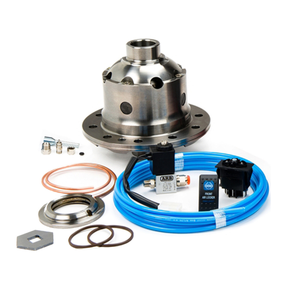
- Page 1 RD244 DANA M200, JL SPORT RR AIR OPERATED LOCKING DIFFERENTIAL INSTALLATION GUIDE...
- Page 2 No liability is assumed for damages resulting in the use of the information contained herein. ARB AIR LOCKER Locking Differentials and AIR LOCKER are trademarks of ARB Corporation Limited. Other product names used herein are for identification purposes only and may be trademarks of their respective owners. ARB 4x4 ACCESSORIES Corporate Head Office 42-44 Garden St...
-
Page 3: Table Of Contents
Table of Contents: 1 Introduction 1.1 Pre-Installation Preparation 1.2 Tool-Kit Recommendations 2 Removing the Existing Differential 2.1 Vehicle Support 2.2 Differential Fluid Drain 2.3 Removing the Axles 2.4 Marking the Bearing Caps 2.5 Checking the Current Backlash Amount 2.6 Removing the Differential Carrier 3 Installing the Air Locker 3.1 Drilling and Tapping the Bulkhead Port 3.2 Assembling the Seal Housing... -
Page 5: Introduction
1 Introduction IMPORTANT : BEFORE ATTEMPTING TO DISMANTLE YOUR VEHICLE FOR THIS INSTALLATION, PLEASE READ THIS INSTALLATION GUIDE IN ITS ENTIRETY, AS WELL AS ALL APPLICABLE SECTIONS OF YOUR VEHICLE MANUFACTURER’S SERVICE MANUAL. Pre-Installation Preparation This booklet is to be used in conjunction with your vehicle manufacturer’s service manual. -
Page 6: Tool-Kit Recommendations
1 Introduction Tool-Kit Recommendations Below is a list of tools and supplies you may need to complete this installation. Requirements for your vehicle may vary. Please consult your vehicle service manual for additional recommendations. Tools 1.2.1 Standard automotive sizes (metric and/or imperial) of sockets, wrenches, Allan keys, and drills. -
Page 7: Removing The Existing Differential
2 Removing the Existing Differential Vehicle Support Safely secure the vehicle on a hoist. We recommend supporting the vehicle on a chassis hoist to keep the differential area at a convenient working height and to leave the wheels and axles free to be rotated and removed. - Page 8 2 Removing the Existing Differential Removal of the Axles Remove the wheels, and brakes according to your vehicle manufacturer’s service manual. Remove both axle shafts according to your vehicle manufacturer’s service manual. IMPORTANT : Collision damage or heavy off-road use of your vehicle in the past may have resulted in some degree of bending in the axle.
-
Page 9: Marking The Bearing Caps
2 Removing the Existing Differential Marking the Bearing Caps Using a small pointed center punch, gently mark the bearing caps in a way that will enable you to know which cap is ‘LEFT’ and which cap is ‘RIGHT’, which way is ‘UP’ and which way is ‘DOWN’. (Fig.1.) HINT : Many installers choose to make one punch mark on... -
Page 10: Checking The Current Backlash Amount
2 Removing the Existing Differential Checking the Current Backlash Amount IMPORTANT: This step is a precautionary measure recommended by ARB due to the fact that some after market ring and pinion sets have been manufactured to run with different backlash settings than those specified by your vehicle manufacturer. -
Page 11: Removing The Differential Carrier
2 Removing the Existing Differential While supporting the pinion gear by holding the pinion flange, rotate the differential in both directions while observing the maximum variation in depth from the indicator (i.e., the highest value minus the lowest value). This value is referred to as the ring and pinion backlash. - Page 12 2 Removing the Existing Differential Figure 3. NOTE : The differential center is heavy and quite difficult to handle when covered in oil. Take care not to drop it. Relieve any tension on the spreader immediately after the differential has been removed.
-
Page 13: Installing The Air Locker
3 Installing the Air Locker Drilling and Tapping the Bulkhead Port An air line port must be drilled and tapped through the differential housing to mount the bulkhead fitting into. Cover the drive pinion and axle tube areas with a rag to protect them from metal filings. -
Page 14: Assembling The Seal Housing
3 Installing the Air Locker Drill an 11.2mm [7/16”] diameter hole through the differential housing square to the outside surface. Tap the hole from the outside using ¼”NPT thread tap. Remove any sharp edges that may chip off from around the hole and fall into the housing. -
Page 15: Approximate Backlash Shimming
3 Installing the Air Locker Lubricate the seal housing running surface on the Air Locker carrier with oil. Carefully install the seal housing by sliding it all of the way onto the seal housing journal with a gentle twisting motion. This will allow the O-rings to engage gently (Fig.6.). - Page 16 3 Installing the Air Locker Using a caliper or similarly accurate measurement method (i.e., able to take accurate measurements within 0.04mm [0.0015”]), measure the distance from the shoulder of the bearing journal to the ring gear mounting face (shown as ‘A’ in Figure 7.) and record this measurement as ‘A’.
-
Page 17: Calculation & Selection Of Backlash Shims
3 Installing the Air Locker Calculation & Selection of Backlash Shims Ideally, the measurement you recorded as ‘C’ from the Air Locker differential will closely match ‘A’ on the existing differential (within 0.1mm [0.004”] ) and then the factory shim can be reused, however, quite often these measurements will vary slightly between one factory differential and the next. -
Page 18: Installing The Carrier Bearings
3 Installing the Air Locker Installing the Carrier Bearings The Air Locker is supplied with a replacement bearing to be used on the left hand side of the diff (flange cap side). Discard the original. Apply a thin film of high pressure grease to the bearing journals of the Air Locker, then press the bearing cones onto the bearing journals as shown in Figure 9. - Page 19 3 Installing the Air Locker Heat the ring gear to between 80 and 100C (175 - 212F) in hot water or in an oven to slightly expand the gear and facilitate assembly. NOTE : NEVER HEAT GEARS WITH A FLAME! This could damage the hardened surface of the gear and result in premature wear or failure.
-
Page 20: Preload Shim Measurement
3 Installing the Air Locker Preload Shim Measurement In order to preload the tapered roller bearings in your Air Locker, measurements need to be taken so that a value can be calculated for the total shim thickness ‘E’ in Figure 11. Figure 11. - Page 21 3 Installing the Air Locker Figure 12. Add the specified preload amount to the end float measurement determined with the feeler gauge to determine a shim amount for ‘E’ (Refer to Figure 11.). PRELOAD + END FLOAT = SHIM PACK ...
-
Page 22: Setting Up The Bulkhead Fitting
3 Installing the Air Locker Setting up the Bulkhead Fitting Apply thread sealant to the outside threads of the bulkhead body. Screw the bulkhead body into the tapped hole, and lightly tighten using a 14mm [9/16”] spanner. Wipe the area clean of any excess thread sealant (inside and outside of the housing). - Page 23 3 Installing the Air Locker Insert the free end of the seal housing tube into the bulkhead fitting until it protrudes approximately 8mm [5/16”] through the other side. From the outside of the housing, assemble one of the small O-rings over the top of the short length of seal housing tube protruding through the bulkhead fitting.
-
Page 24: Profiling The Seal Housing Tube
3 Installing the Air Locker Profiling the Seal Housing Tube With the seal housing tube now firmly secured into the bulkhead fitting, bend the tube so that it closely follows the profile of the differential without interfering with the bearing cap, diff housing or Air Locker (Fig. -
Page 25: Bench Testing The Air Locker
3 Installing the Air Locker Bench Testing the Air Locker 3.10 To test the Air Locker, when 620kPa [90 PSI] shop air is applied to the seal housing tube, the Air Locker should engage. Check all fittings and the seal housing for air leaks. ... -
Page 26: Reinstalling Differential And Axles
3 Installing the Air Locker Reinstalling Differential and Axles 3.11 Install the axles and cover plate as detailed in your vehicle service manual. NOTE : Be careful not to damage the axle shaft oil seals when installing the axle. Support the axle’s entire weight where possible. -
Page 27: Installing The Air System
4 Installing the Air System Mounting the Solenoid Connection to an ARB Air Compressor (Fig. 17.) 4.1.1 Remove one of the 1/8” BSP plugs from its port in the compressor tank. Apply Teflon paste to the 1/8” BSP nipple on the solenoid and insert it into the port and tighten. - Page 28 4 Installing the Air System Connection to an Alternate Air Source 4.1.2 For ease of installation, quality of air supply, and a high level of dependability from your Air Locker(s), ARB strongly recommends use of a genuine ARB Air Compressor, however, the Air Locker air system can be operated on any alternate air source that meets each of the following guidelines: ...
-
Page 29: Running & Securing The Air Line
4 Installing the Air System Running and Securing the Air Line The path taken by the air line from your air source (i.e., compressor) to your Air Locker is unique to your vehicle and the position of your air source. Plan ahead carefully when running the air line and always follow these guidelines: ... -
Page 30: Connection To The Bulkhead Fitting
4 Installing the Air System NOTE : To remove the air line from the push-in fitting; push the air line as far into the fitting as possible and hold, push inward on the flange, and then pull the air line free of the fitting. - Page 31 4 Installing the Air System Push the airline into the compression fitting body and screw the outer nut down onto it. Using a 12mm spanner, tighten the outer nut onto the compression fitting body. NOTE : Some force is required to crush the ferrule, however the outer compression nut will tighten against a stop.
-
Page 32: Mounting & Connecting The Electrical System
5 Mounting & Connecting the Electrical System Mounting the Actuator Switch(es) Air Locker actuator switch(es) can be easily panel mounted inside the vehicle in a 21mm x 36.5mm [0.83” x 1.44”] rectangular cutout. NOTE : Only attach the cover plate to the face of the switch once the switch has been mounted and wired correctly as the cover plates are designed to be difficult to remove. -
Page 33: Wiring The Actuator System
5 Mounting & Connecting the Electrical System Wiring the Actuator System Connection to an ARB AIR COMPRESSOR 5.2.1 When wiring the Air Locker actuator switch(es) and solenoid(s) to an ARB Air Compressor, all connections can easily be set up directly from the supplied wiring loom. - Page 34 5 Mounting & Connecting the Electrical System SWITCH TERMINAL IDENTIFICATION Figure 21. Connection to an Alternate Air Source 5 .2.2 When connecting the actuation switch to an alternate air source, the switch(es) should be wired according to figures 22. and 23. depending on whether one or two Air Lockers will be installed in the vehicle.
- Page 35 5 Mounting & Connecting the Electrical System Dual Air Locker System 5.2.2.2 If two Air Lockers are to be installed in the system, ARB recommends that the switches and solenoids be wired according to figure 23. For safety reasons, this configuration allows SOLENOID 2 to be actuated only if SOLENOID 1 is already on.
-
Page 36: Testing & Final Assembly
6 Testing & Final Assembly Leak Testing With the vehicle parked and the engine off, turn the compressor on and wait until the air system is fully charged. NOTE : With the Air Locker(s) disengaged, the air source (i.e., compressor) should not have to recharge over time. -
Page 37: Filling The Differential
6 Testing & Final Assembly Turn the compressor (or alternate air source) on to charge the air supply up to its maximum pressure. Rotate one wheel by hand. The wheel should rotate freely and the opposite wheel should be turning in the opposite direction without any resistance or mechanical noise from within the differential. -
Page 38: Post-Installation Check List
6 Testing & Final Assembly Post-Installation Check List Now that the Air Locker installation has been completed, ARB recommends that you take the time to complete the following check list just to insure that you haven’t missed any of the vital steps. ... -
Page 39: Parts List
7 Parts List RD244 DANA M200, JL SPORT RR Exploded Assembly Diagram (See itemized parts list overleaf) Figure 24. Specifications Axle Spline 29 tooth, Ø31.5mm [1.24”] Ratio Supported Ring Gear ID 121.3mm [4.776”] Ring Gear OD 200.0mm [7.874”] Ring Gear Bolts 10 bolts on Ø145.5mm [5.728”]... -
Page 40: Itemized Parts List
7 Parts List Itemized Parts List (See exploded diagram Figure 24.) ITEM # DESCRIPTION PART # NOTES FLANGE CAP KIT 028525SP CLUTCH GEAR & WAVESPRING KIT 050902SP WAVESPRING 150702SP LONG CROSS SHAFT 061302SP SHORT CROSS SHAFT 061402SP SIDE GEAR SEE NOTE PINION THRUST WASHER SEE NOTE DIFFERENTIAL CASE...
Need help?
Do you have a question about the RD244 and is the answer not in the manual?
Questions and answers