Table of Contents
Advertisement
Quick Links
Advertisement
Table of Contents

Related Manuals for Airlocker RD139


Summary of Contents for Airlocker RD139
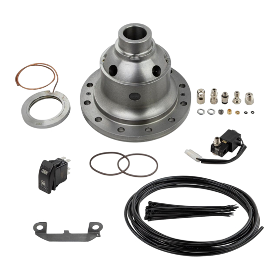
- Page 1 RD139 AAM 11.5” REAR AIR OPERATED LOCKING DIFFERENTIAL INSTALLATION GUIDE...
- Page 2 No liability is assumed for damages resulting in the use of the information contained herein. ARB AIR LOCKER Locking Differentials and AIR LOCKER are trademarks of ARB Corporation Limited. Other product names used herein are for identification purposes only and may be trademarks of their respective owners. ARB 4x4 ACCESSORIES Corporate Head Office 42-44 Garden St...
-
Page 3: Table Of Contents
Table of Contents: 1 Introduction 1.1 Pre-Installation Preparation 1.2 Tool-Kit Recommendations 2 Removing the Existing Differential 2.1 Vehicle Support 2.2 Differential Fluid Drain 2.3 Removing the Axles 2.4 Marking the Bearing Caps 2.5 Checking the Current Backlash Amount 2.6 Removing the Differential Carrier 3 Installing the Air Locker 3.1 Mounting the Ring Gear 3.2 Drilling and Tapping the Bulkhead Port... -
Page 5: Introduction
1 Introduction IMPORTANT : BEFORE ATTEMPTING TO DISMANTLE YOUR VEHICLE FOR THIS INSTALLATION, PLEASE READ THIS INSTALLATION GUIDE IN ITS ENTIRETY, AS WELL AS ALL APPLICABLE SECTIONS OF YOUR VEHICLE MANUFACTURER’S SERVICE MANUAL. Pre-Installation Preparation This booklet is to be used in conjunction with your vehicle manufacturer’s service manual. -
Page 6: Tool-Kit Recommendations
1 Introduction Tool-Kit Recommendations Below is a list of tools and supplies you may need to complete this installation. Requirements for your vehicle may vary. Please consult your vehicle service manual for additional recommendations. Tools 1.2.1 Standard automotive sizes (metric and/or imperial) of sockets, wrenches, Allan keys, and drills. -
Page 7: Removing The Existing Differential
2 Removing the Existing Differential Vehicle Support Safely secure the vehicle on a hoist. We recommend supporting the vehicle on a chassis hoist to keep the differential area at a convenient working height and to leave the wheels and axles free to be rotated and removed. -
Page 8: Marking The Bearing Caps
2 Removing the Existing Differential Marking the Bearing Caps Using a small pointed center punch, gently mark the bearing caps in a way that will enable you to know which cap is ‘LEFT’ and which cap is ‘RIGHT’, which way is ‘UP’ and which way is ‘DOWN’. (Fig.1.) ... -
Page 9: Checking The Current Backlash Amount
2 Removing the Existing Differential Checking the Current Backlash Amount IMPORTANT: This step is a precautionary measure recommended by ARB due to the fact that some after market ring and pinion sets have been manufactured to run with different backlash settings than those specified by your vehicle manufacturer. -
Page 10: Removing The Differential Carrier
2 Removing the Existing Differential Removing the differential carrier Remove the adjuster nut locking tabs. Remove the bearing caps. Loosen the adjuster nuts. Carefully remove the differential carrier from the housing. Remove the tapered roller bearings from the differential carrier with a bearing puller. -
Page 11: Installing The Air Locker
3 Installing the Air Locker Mounting the Ring Gear Remove the bolts that hold the ring gear in place. Using a plastic or copper hammer, tap in a circle around the ring gear to separate it from the differential carrier. ... -
Page 12: Drilling And Tapping The Bulkhead Port
3 Installing the Air Locker Figure 4. Drilling and Tapping the Bulkhead Port An air line port must be drilled and tapped through the differential housing to mount the bulkhead fitting into. Mark a spot on the top of the outside of the differential housing that will be clear of the Air Locker once the seal housing tube has been installed. -
Page 13: Assembling The Seal Housing
3 Installing the Air Locker Cover the drive pinion and axle tube areas with a rag to protect them from metal filings. Drill an 11.2mm [7/16”] diameter hole through the differential housing square to the outside surface. Tap the hole from the outside using ¼”NPT thread tap. ... -
Page 14: Installing The Carrier Bearings
3 Installing the Air Locker Lubricate the seal housing running surface on the Air Locker carrier with oil. Carefully install the seal housing by sliding it all of the way onto the seal housing journal with a gentle twisting motion. This will allow the O-rings to engage gently (Fig. -
Page 15: Setting The Backlash
3 Installing the Air Locker Setting the Backlash Assemble the bearing cups onto the Air Locker. Loosen the adjuster nuts in the housing so that they are as far apart as possible. Insert the Air Locker into the housing and rotate it until it is fully in mesh with the pinion gear, with the seal housing tube pointing straight out of the housing. - Page 16 3 Installing the Air Locker Adjust the backlash using an adjuster nut wrench to tighten or loosen the adjuster nuts as required. (Refer to your vehicle service manual.) Recheck backlash as before, repeating this procedure until backlash is within the specified amount. IMPORTANT: It is critical to set up bearing pre-load when a differential is installed.
-
Page 17: Setting Up The Bulkhead Fitting
3 Installing the Air Locker Setting up the Bulkhead Fitting Apply thread sealant to the outside threads of the bulkhead body. Screw the bulkhead body into the tapped hole, and lightly tighten using a 14mm [9/16”] spanner. Wipe the area clean of any excess thread sealant (inside and outside of the housing). - Page 18 3 Installing the Air Locker While holding the seal housing tube into the bulkhead fitting, insert the chamfered end of the center compression nut over the extended tube as shown in the assembly diagram (Fig. 10.), and screw it into the bulkhead body, and tighten using Pozidriv #3 screwdriver.
-
Page 19: Profiling The Seal Housing Tube
3 Installing the Air Locker Profiling the Seal Housing Tube With the seal housing tube now firmly secured into the bulkhead fitting, bend the tube so that it closely follows the profile of the differential. Cable tie the seal housing tube to the seal housing retaining plate. -
Page 20: Bench Testing The Air Locker
3 Installing the Air Locker Bench Testing the Air Locker To test the Air Locker, when 620kPa [90 PSI] shop air is applied to the seal housing tube, the Air Locker should engage. Check all fittings and the seal housing for air leaks. ... -
Page 21: Reinstalling The Differential & Axles
3 Installing the Air Locker Reinstalling Differential and Axles Install the axles and cover plate as detailed in your vehicle service manual. NOTE : Be careful not to damage the axle shaft oil seals when installing the axle. Support the axle’s entire weight where possible. -
Page 22: Installing The Air System
4 Installing the Air System Mounting the Solenoid Connection to an ARB Air Compressor (Fig.14.) 4.1.1 Remove one of the 1/8” BSP plugs from its port in the compressor tank. Apply Teflon paste to the 1/8” BSP nipple on the solenoid and insert it into the port and tighten. - Page 23 4 Installing the Air System Connection to an Alternate Air Source 4.1.2 For ease of installation, quality of air supply, and a high level of dependability from your Air Locker(s), ARB strongly recommends use of a genuine ARB Air Compressor, however, the Air Locker air system can be operated on any alternate air source that meets each of the following guidelines: ...
-
Page 24: Running & Securing The Air Line
4 Installing the Air System Running and Securing the Air Line The path taken by the air line from your air source (i.e., compressor) to your Air Locker is unique to your vehicle and the position of your air source. Plan ahead carefully when running the air line and always follow these guidelines: ... -
Page 25: Connection To The Bulkhead Fitting
4 Installing the Air System NOTE : To remove the air line from the push-in fitting; push the air line as far into the fitting as possible and hold, push inward on the flange, and then pull the air line free of the fitting. - Page 26 4 Installing the Air System Push the airline into the compression fitting body and screw the outer nut down onto it. Using a 12mm spanner, tighten the outer nut onto the compression fitting body. NOTE : Some force is required to crush the ferrule, however the outer compression nut will tighten against a stop.
-
Page 27: Mounting & Connecting The Electrical System
5 Mounting & Connecting the Electrical System Mounting the Actuator Switch(es) Air Locker actuator switch(es) can be easily panel mounted inside the vehicle in a 21mm x 36.5mm [0.83” x 1.44”] rectangular cutout. NOTE : Only attach the cover plate to the face of the switch once the switch has been mounted and wired correctly as the cover plates are designed to be difficult to remove. -
Page 28: Wiring The Actuator System
5 Mounting & Connecting the Electrical System Wiring the Actuator System Connection to an ARB AIR COMPRESSOR 5.2.1 When wiring the Air Locker actuator switch(es) and solenoid(s) to an ARB Air Compressor, all connections can easily be set up directly from the supplied wiring loom. - Page 29 5 Mounting & Connecting the Electrical System SWITCH TERMINAL IDENTIFICATION Figure 18. Connection to an Alternate Air Source 5 .2.2 When connecting the actuation switch to an alternate air source, the switch(es) should be wired according to figures 19. and 20. depending on whether one or two Air Lockers will be installed in the vehicle.
- Page 30 5 Mounting & Connecting the Electrical System Dual Air Locker System 5.2.2.2 If two Air Lockers are to be installed in the system, ARB recommends that the switches and solenoids be wired according to figure 20. For safety reasons, this configuration allows SOLENOID 2 to be actuated only if SOLENOID 1 is already on.
-
Page 31: Testing & Final Assembly
6 Testing & Final Assembly Leak Testing With the vehicle parked and the engine off, turn the compressor on and wait until the air system is fully charged. NOTE : With the Air Locker(s) disengaged, the air source (i.e., compressor) should not have to recharge over time. -
Page 32: Filling The Differential
6 Testing & Final Assembly Turn the compressor (or alternate air source) on to charge the air supply up to its maximum pressure. Rotate one wheel by hand. The wheel should rotate freely and the opposite wheel should be turning in the opposite direction without any resistance or mechanical noise from within the differential. -
Page 33: Post-Installation Check List
6 Testing & Final Assembly Post-Installation Check List Now that the Air Locker installation has been completed, ARB recommends that you take the time to complete the following check list just to insure that you haven’t missed any of the vital steps. ... - Page 34 6 Testing & Final Assembly...
-
Page 35: Parts List
7 Parts List AAM 11.5” Rear RD139 Exploded Assembly Diagram (See itemized parts list overleaf) Figure 21. Specifications 30 tooth, Ø39.1mm [1.54”] Axle Spline Ratio Supported 187.2mm [7.37”] Ring Gear ID 292.1mm [11.5”] Ring Gear OD 12 bolts on Ø220.0mm [8.66”]... -
Page 36: Itemized Parts List
7 Parts List Itemized Parts List (See exploded diagram Figure 21.) ITEM # DESCRIPTION PART # NOTES FLANGE CAP KIT 028603SP BONDED SEAL 160703SP CLUTCH GEAR & WAVESPRING KIT 050907SP CLUTCH GEAR & RETURN SPRINGS KIT 050807SP SPIDER BLOCK 070402SP LONG CROSS SHAFT 061501SP PINION GEAR...
Need help?
Do you have a question about the RD139 and is the answer not in the manual?
Questions and answers