Advertisement
Quick Links
Advertisement

Related Manuals for Skip Model Designs 41% Ultimate 10-300


Summary of Contents for Skip Model Designs 41% Ultimate 10-300
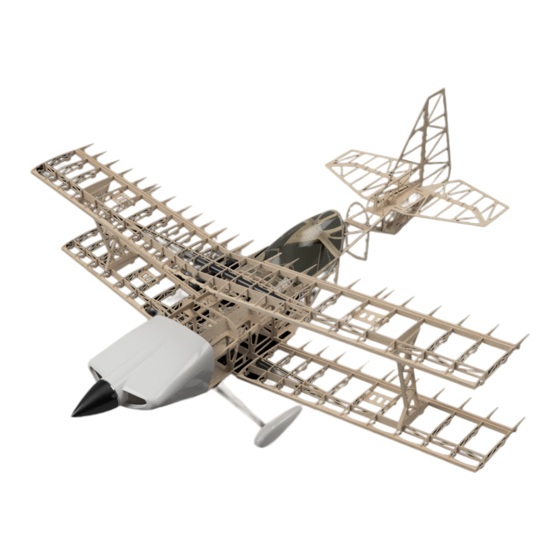
- Page 1 41% Unitmate 10-300 41% Unitmate 10-300...
- Page 2 Skip Model Designs provides high-quality aircraft and components to it’s customers and end users. These aircraft and components are assembled by the end user to produce a flying model. It is beyond skip model design’s to monitor the end user’s completed aircraft. Therefore, Skip Model Designs in no way accepts or assumes responsibility or liability for damages resulting from the end user assembled product.
- Page 3 Elevator and Stab Assembley With Any model build, It is important to test fit components together before gluing ( Where applicable). 5 Minutes test Fitting can save hours of Unpicking. To build ANY COMPONENT of this model, Please make sure you have a large enough area to work safely, and that your work bench for the next few months is clean, tidy and most importantly FLAT First Part of the build is the elevator and Stab( The most...
- Page 4 The Front of the Elevator is to have a 45% chamfer to each side. This will give you 45 Degrees Of Move- ment, Please Adjust to your Flying Style, But we do not recommend more than 50 Degrees or less than 30 Degrees.
- Page 5 Rudder Assembley Construction is similar to elevator using the same 6.5mm x 9.5mm Spruce and 6.5mm x 9.5mm Balsa. However, the Rudder and Fin is only 16m Thick, So the orientation of the Balsa and Spruce changes tro lye on the 9.5m Side. finished thickness is 16mm The Fin Rear is to have the Spruce Glued to it with epoxy.
- Page 7 Fuselage Assembley In The fuselage, You will find alot of parts Labled with acronym’s. Once you get the hang on how they are labled, and meanings like SD ( Servo Doubler), MUCP ( Main UnderCarriage Plate) it will be easy. So you have built the elevators and rudder? Congrats..
- Page 8 Ok..So we may have lied about not doing the first 4 ribs first, We thought we would put your mind at ease..Then Jump Straight in to it!..Element of surprise :) With the model been built upside down, this ensures the entire plane is built true and straight.
- Page 9 Once the fuselage is dried, you now need to add the undercarriage Side doubler, Undercarriage Doubler and Main UC Plate. Use 30 Minute Epoxy, Before Gluing the Main UC Plate in place. Make sure the Undercarriage doubler is covered with epoxy.
- Page 10 Leave F1 Hanging over the edge of the deck and now add all other fuselage ribs * F6 - F9 - Ensure these are square to fuselage, use super glue to stick in place. The Following needs to be glues with epoxy * Rear UC Sides * Rear UC Plate...
- Page 11 Fit The 5mm x 9.5mm Balsa wood Stringers to the Fuselage. You will need to join these with a scarf joint. Use Superglue to a good strong bond. Ensure these run in to the Rear UC Sides. We recommend adding a joining strip inside the rear UC area Dont Forget to add me hidden here :) These Balsa Stringers are only between...
- Page 12 Add FLWM to the Fuselage Sides. The Phenolic tube can be added to the model. You will need to notch the Obechi Middle Strip to get the Phenolic in place. Glue in place with Epoxy. After all of this is done and Glues, You can now flip the model over and take a look at your lovely Boat Hull..
- Page 13 FT2, F3T AND F4T Can be glued in place Using epoxy. You can also at this point add TWM Rear Turtle Deck Ribs can also be added, use CA to get the angle of F6T Correct. These Can be glues with Superglue. Do Not Place F9T in Place Just yet The Rudder Stab Can be added to the fuselage.
- Page 14 A small Strip of balsa wood can be glued between the spruce on the stabs. Superglue will be perfect for this.
- Page 15 In the Kit, there is also 4 Parts Called STM. These parts are used to set the Elevator Angles Put the 8mm Carbon through the Stab AND through STM Both Sides. In the Kit you will also find 2 x Alignment tool for the Elevators.
- Page 16 After the elevators are mounted correcly, The 4mm x 4mm Stringer can now be added to the rear turtle deck! Superglue is fine for this. Assemble the engine box using epoxy., Make sure the engine box has right hand thrust ( Like the shown photo) When the box is assembled, Epoxy all mating faces and fit to F1.
- Page 17 on F4 and F2 you now need to add the steel work for the wings, these are in the Ali Pack supplied with the Kit. ON F4 AND F2 the ali fits in the same place. as shown on drawing, The Rear UC Steelwork location is shown on the plans Once these are in place, we are up to sheeting the...
- Page 18 There are also a few other areas at the bottom of the model that will need sheeting to make things neat for covering and Rudder Control Wire Exits. Underside sheeting...
- Page 19 Continue to sheet the model in 2.4mm balsa as the photos show.. DO NOT SHEET THE FOR- WARD TURTLE DECK JUST YET, Please note, you will need to make a fillet here that blends in to the UC plate. This is quite difficult to do as it has to profile the wing shape as well.
- Page 20 The Cockpit frame can now be assembled on the model, We recommend using greese proof paper, so it does now stick to the model. Balsa stringers are to be added in the designated places on formers, proir to sheeting, All of the cockpit frame can be assembled with superglue The Cockpit frame is sheeted as shown in the image.
- Page 21 Time To align the top wings The Interplain Struts are fully sheeted both sides with 3.2mm Balsa. In the woods, you will also find the hard point woods that are to be used to hold the 3mm captive nuts,...
- Page 22 Time To align the top wings TO MAKE THINGS EASY, YOU CAN DRILL AND BOLT THE INTER- PLANE TO THE BOTTOM WING. PLEASE DO NOT GLUE AT THIS POINT. IT IS ONLY TO HOLD IN PLACE. MAKE SURE TO ADD PACKING UNDER BOTTOM WINGS TO KEEP LEVEL.
Need help?
Do you have a question about the 41% Ultimate 10-300 and is the answer not in the manual?
Questions and answers