Advertisement
Quick Links
SERVICE MANUAL
Ver. 1.0 2012.11
9-893-613-01
Sony Corporation
2012K33-1
©
2012.11
Published by Sony Techno Create Corporation
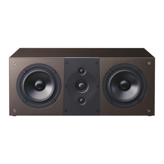
SS-NA8ES
SPECIFICATIONS
Speaker system
3-way 6-driver speaker system, Bass reflex
Speaker unit
Woofer: 165 mm (6.5 in), cone type (2)
Midrange: 130 mm (5.25 in), cone type (1)
Tweeter: Main tweeter, 25 mm (1 in),
dome type (1)
Assist tweeter, 19 mm (0.75 in),
dome type (2)
Rated impedance
4 ohms
Maximum input power
100 watts
Sensitivity
90 dB (2.83 V, 1 m)
Frequency response
45 Hz - 45,000 Hz
Dimensions (w/h/d)
Approx. 255 × 990 × 415 mm
1
(10
/
× 39 × 16
8
Mass
Approx. 32 kg (70 lb 9 oz)
Supplied accessories
Cleaning cloth (1)
Design and specifications are subject to change without notice.
Canadian Model
3
/
in)
8
SPEAKER SYSTEM
US Model
AEP Model
UK Model
Advertisement

Related Manuals for Sony SS-NA8ES


Summary of Contents for Sony SS-NA8ES
- Page 1 × 39 × 16 Mass Approx. 32 kg (70 lb 9 oz) Supplied accessories Cleaning cloth (1) Design and specifications are subject to change without notice. SPEAKER SYSTEM 9-893-613-01 Sony Corporation 2012K33-1 © 2012.11 Published by Sony Techno Create Corporation...
-
Page 2: Section 1 Servicing Notes
SS-NA8ES SECTION 1 SERVICING NOTES NOTE THE SPEAKER UNITS REPLACING 3 PACKING (C) is not reused. When Assist tweeter is removed, Refer to “2. DISASSEMBLY” (page 4 or subsequent) for the re- please be sure to exchange PACKING (C). placement procedure of each loudspeaker unit. - Page 3 SS-NA8ES ABOUT HANDLING OF A LOUDSPEAKER UNIT (WOOFER) Do not put the corn side of a loudspeaker unit (woofer) on a fl oor etc. When placing a corn side, put on a fl oor etc. after making into a stand the parts supplied to a new loudspeaker unit.
-
Page 4: Section 2 Disassembly
SS-NA8ES SECTION 2 DISASSEMBLY • This set can be disassembled in the order shown below. 2-1. DISASSEMBLY FLOW 2-5. TERMINAL BOARD ASSY (TB1) 2-2. GRILLE FRAME ASSY (Page 7) (Page 4) 2-3. TWEETER ASSY 2-6. LOUDSPEAKER (13 cm) 2-7. LOUDSPEAKER (13 cm) - Page 5 SS-NA8ES 2-3. TWEETER ASSY Note 2: When installing the tweeter assy, after each screw holes of the tweeter assy and packing (A) are aligned, attach it to the speaker cabinet. speaker cabinet 5 tweeter assy Note 6: When installing the tweeter assy, be careful not to put wires.
- Page 6 SS-NA8ES 2-4. LOUDSPEAKER (1.9 cm) (ASSIST TWEETER) (SP3, SP4) Note 1: When exchanging the loudspeaker (1.9 cm) (assist tweeter) (SP3, SP4), refer to “NOTE THE SPEAKER UNITS REPLACING” on page 2 2 two screws (BV B3.5 Note 3: When tightening screws, be 2 two screws (BV B3.5...
- Page 7 SS-NA8ES 2-5. TERMINAL BOARD ASSY (TB1) Note 1: When installing screws (3.5 × 20), follow the installing procedure in the numerical order given. tightening torque : .2 0.05 3 terminal (black) 4 terminal packing 3 terminal (red) 2 Pull out the terminal 1 four screws board assy (TB1).
- Page 8 SS-NA8ES 2-6. LOUDSPEAKER (13 cm) (WOOFER: LEFT SIDE) (SP1) Note 1: When exchanging the loudspeaker (13 cm) (woofer: left side) (SP1), refer to “NOTE THE SPEAKER UNITS REPLACING” on page 2. Note 3: Check that the caulking portion of a terminal is outside suitable.
- Page 9 SS-NA8ES 2-7. LOUDSPEAKER (13 cm) (WOOFER: RIGHT SIDE) (SP2) Note 1: When exchanging the loudspeaker (13 cm) (woofer: right side) (SP2), refer to “NOTE THE SPEAKER UNITS REPLACING” on page 2. Note 3: Check that the caulking portion of a terminal is outside suitable.
- Page 10 SS-NA8ES 2-8. WO BOARD BLOCK – Speaker cabinet left inner side sectional view – 2 Remove four catchers from four shafts of speaker cabinet. speaker cabinet shaft shaft 1 tapping screw shaft (BV3.5) tightening torque: shaft blue brown brown blue...
- Page 11 SS-NA8ES 2-9. TW BOARD BLOCK speaker cabinet – Speaker cabinet right inner side sectional view – 2 Remove four catchers from four shafts of speaker cabinet. shaft shaft shaft shaft 1 tapping screw (BV3.5) 3 After rotating TW board 90° within a speaker 4 TW board block cabinet, it pulls out from a speaker cabinet.
-
Page 12: Section 3 Exploded View
SS-NA8ES SECTION 3 EXPLODED VIEW Note: • -XX and -X mean standardized parts, so • The mechanical parts with no reference they may have some difference from the number in the exploded views are not sup- original one. plied. • Items marked “*” are not stocked since •... -
Page 13: Section 4 Accessories
SS-NA8ES SECTION 4 ACCESSORIES Ref. No. Part No. Description Remark 2-597-467-02 CLEANING CLOTH 4-289-154-11 INSTRUCTION MANUAL (ENGLISH, FRENCH, SPANISH) 4-289-154-21 INSTRUCTION MANUAL (GERMAN, DUTCH, ITALIAN, POLISH) (AEP, UK) 4-289-154-31 INSTRUCTION MANUAL (RUSSIAN) (AEP, UK) 4-289-154-41 INSTRUCTION MANUAL (NORWEGIAN, SWEDISH, DANISH, FINNISH) - Page 14 SS-NA8ES REVISION HISTORY Ver. Date Description of Revision 2012.11...
Need help?
Do you have a question about the SS-NA8ES and is the answer not in the manual?
Questions and answers