Table of Contents
Advertisement
Available languages
Available languages
Quick Links
Speaker System
Operating Instructions
Mode d'emploi
Page 16
Bedienungsanleitung
お買い上げいただきありがとうございます。
電気製品は、安全のための注意事項を守らないと、
警告
火災や人身事故になることがあります。
この取扱説明書には、事故を防ぐための重要な注意事項と製品の取り扱いかたを示
してあります。この取扱説明書をよくお読みのうえ、製品を安全にお使いください。
お読みになったあとは、いつでも見られるところに必ず保管してください。
SS-X500A
© 1998 by Sony Corporation
Manual de instrucciones
Page 2
Istruzioni per l'uso
取扱説明書
Seite 30
3-864-740-03(1)
Página 46
Pagina 60
74
ペ−ジ
Advertisement
Chapters
Table of Contents

Related Manuals for Sony SS-X500A


Summary of Contents for Sony SS-X500A
- Page 1 3-864-740-03(1) Speaker System Manual de instrucciones Operating Instructions Página 46 Page 2 Istruzioni per l’uso Mode d’emploi Page 16 Pagina 60 取扱説明書 Bedienungsanleitung ペ−ジ Seite 30 お買い上げいただきありがとうございます。 電気製品は、安全のための注意事項を守らないと、 警告 火災や人身事故になることがあります。 この取扱説明書には、事故を防ぐための重要な注意事項と製品の取り扱いかたを示 してあります。この取扱説明書をよくお読みのうえ、製品を安全にお使いください。 お読みになったあとは、いつでも見られるところに必ず保管してください。 SS-X500A © 1998 by Sony Corporation...
- Page 2 English WARNING To prevent fire or shock hazard, do not expose the unit to rain or moisture.
-
Page 3: Table Of Contents
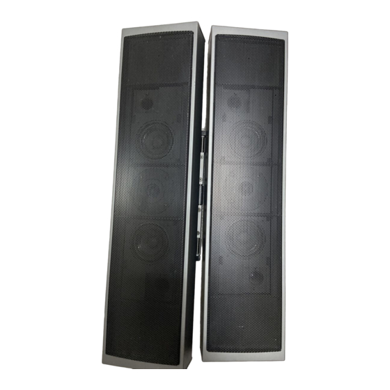
English Table of Contents Features The SS-X500A is a two-way bass reflex speaker system Features ..............3 which adopts a cone-type woofer and tweeter. This speaker Precautions ..............4 system is designed for use with the PFM-500A1WU/A1WE Parts List ..............5 flat panel monitor. -
Page 4: Precautions
They may damage the surface finish, or In the event of any problems with the operation of the unit, impair the operation of the shutter adaptor. contact your Sony service representative. Ventilation Do not wrap the unit in a cloth, etc., during operation. This may cause the internal temperature to rise excessively and the unit to malfunction. -
Page 5: Parts List
Parts List Speaker (2) Speaker attachment screw Speaker cord 2.5 m (2) Bracket (2) (black, M5×9) (6) Speaker cord holder (4) Bracket attachment screw (gray, M4×14) (8) Ferrite filter (4) -
Page 6: Parts Identification
Parts Identification Wall attachment hole Angle lock screw Speaker attachment holes Bracket attachment Woofer holes Tweeter Woofer Wall attachment holes Speaker attachment holes Angle lock screw Wall attachment hole Speaker Rear Bracket Speaker Front... -
Page 7: Installing The Speakers
Installing the Speakers Install the right/left speakers using the brackets as follows: Speaker Right Speaker Left Speaker attachment Match the speaker attachment holes on the speaker to holes the speaker attachment holes on the bracket. Attach the brackets to the speakers with the supplied M5 screws (black, 3 screws each for left and right holes). - Page 8 Installing the Speakers Hook the bracket attachment holes on the bracket onto the screws temporarily tightened in Step 3. Install the speakers. Tighten the screws completely with a coin and lock the speakers. Connect the speaker to the monitor with the supplied cord.
-
Page 9: Installing The Speakers On A Wall
Installing the Speakers on a Wall You can install the speakers on a wall using the wall When you use a bracket attachment screw holes of the brackets and speakers. You can change the speaker angles if you have installed the speakers with the brackets. -
Page 10: Changing The Speaker Angles
Installing the Speakers Changing the Speaker Angles After installing the speakers on the monitor, you can change the speaker angle. To move the speakers far forward, follow the steps below: Loosen the M5 screws (black, 3 screws each for right PFM-500A1WU/A1WE Front and left that fix the speakers and the brackets). -
Page 11: Attaching The Ferrite Filters
Tip of the speaker cord Approx. 5 cm Ferrite filters (2 inches) Speaker cord to speaker terminal on the PFM-500A1WU/A1WE Approx. 5 cm flat panel monitor (2 inches) to speaker terminal on the SS-X500A speaker system... -
Page 12: Connecting To The Monitor
Connecting to the Monitor Before connecting the speakers to the monitor, be sure to turn off the monitor’s power. Connect the speakers to the monitor while the panel cover SPEAKERS Press the button on the monitor is open. (6-16 Ω) and insert the For details on how to install the speakers to the monitor, see buttons... - Page 13 To install the speaker cord holders Securely insert the As shown in the figure, insert the holders into the holes on holders into the holes the ventilation openings. on the ventilation Evenly space the holders and insert them under the monitor openings.
-
Page 14: Connecting To The Amplifier
Connecting to the Amplifier Connect the cord to the speaker terminals of the AV • Do not connect the speaker system to the monitor and an amplifier. amplifier. Doing so may cause a large amount of current to flow into the monitor from the amplifier via the speaker Notes cord, resulting in damage to the monitor. -
Page 15: Specifications
Specifications Speaker system Mass Approx. 3.5 kg (7 lb 11 oz) (net per speaker) Woofer × 2, magnetically shielded Approx. 1.1 kg (2 lb 7 oz) (net per bracket) Tweeter × 1, magnetically shielded Supplied accessories Speaker unit 8 cm (3 inches), cone type Speaker cord (2, 2.5 m) 2.5 cm (1 inch), dome type... - Page 16 Français AVERTISSEMENT Afin d’eviter tout risque d’incendie ou d’électrocution, ne pas exposer cet appareil à la pluie ou à l’humidité.
-
Page 17: Caractéristiques
Français Table des matières Caractéristiques Le SS-X500A est un système de haut-parleurs bass reflex à Caractéristiques ............17 deux voies intégrant un woofer et un tweeter en cône. Ce Précautions .............. 18 système de haut-parleurs est conçu en vue d’une utilisation Liste des composants .......... -
Page 18: Précautions
Si vous rencontrez des problèmes d’utilisation avec cet appareil, consultez un représentant du service après-vente Sony. Ventilation N’enveloppez pas l’unité dans du tissu, etc., en cours de fonctionnement. Cela risque d’entraîner une augmentation excessive de la température intérieure et un... -
Page 19: Liste Des Composants
Liste des composants Haut-parleur (2) Support (2) Vis de fixation de haut-parleur Cordon de haut-parleur (noir, M5×9) (6) (2,5 m) (2) Crochet à cordon de haut-parleur (4) Vis de fixation de support (gris, M4×14) (8) Filtre en ferrite (4) -
Page 20: Identification Des Composants
Identification des composants Orifice de fixation murale Vis de réglage d’angle Orifices de fixation de haut-parleur Orifices de fixation de Woofer support Tweeter Woofer Orifice de fixation murale Orifices de fixation de haut-parleur Vis de réglage Orifice de d’angle fixation murale Haut-parleur Haut-parleur... -
Page 21: Installation Des Haut-Parleurs
Installation des haut-parleurs Installez les haut-parleurs gauche et droit à l’aide des Haut-parleur Haut-parleur Orifices de supports de montage en procédant comme suit : gauche droit fixation de haut-parleur Alignez les orifices de fixation de haut-parleur du haut- parleur sur les orifices correspondants du support. Fixez les supports aux haut-parleurs à... - Page 22 Installation des haut-parleurs Accrochez provisoirement les orifices de fixation de support aux vis que vous avez serrées à l’étape 3. Installez les haut-parleurs. Serrez les vis à fond à l’aide d’une pièce de monnaie ou d’un tournevis et bloquez les haut-parleurs. Raccordez le haut-parleur au moniteur au moyen du cordon fourni.
-
Page 23: Installation Des Haut-Parleurs Au Mur
Installation des haut-parleurs au mur Vous pouvez installer les haut-parleurs au mur à l’aide des Si vous utilisez un support trous de vissage pour fixation murale des supports et des haut-parleurs. Si vous avez installé les haut-parleurs sur les supports, vous pouvez en changer l’angle d’orientation. -
Page 24: Changement De L'angle Des Haut-Parleurs
Installation des haut-parleurs Changement de l’angle des haut-parleurs Après avoir installé les haut-parleurs sur le moniteur, vous pouvez changer l’angle des haut-parleurs. Pour faire pivoter les haut-parleurs tout à fait vers l’avant, procédez comme suit : Desserrez les vis M5 (noires, 3 à gauche et à droite, qui PFM-500A1WU/A1WE Avant fixent les haut-parleurs et les supports). -
Page 25: Installation Des Filtres En Ferrite
Extrémité du cordon de haut-parleur Approx. 5 cm Filtres en ferrite (2 pouces) Cordon de haut-parleur vers la borne de haut-parleur du moniteur à écran plat Approx. 5 cm PFM-500A1WU/A1WE (2 pouces) vers la borne de haut-parleur de l’enceinte SS-X500A... -
Page 26: Raccordement Au Moniteur
Raccordement au moniteur Avant de raccorder les haut-parleurs au moniteur, veillez à mettre le moniteur hors tension. Raccordez les haut-parleurs au moniteur pendant que le Appuyez sur le SPEAKERS couvercle de panneau du moniteur est ouvert. (6-16 Ω) bouton et Boutons introduisez le fil Pour plus de détails sur l’installation des haut-parleurs sur... - Page 27 De même, pour le cordon au haut-parleur gauche, tirez Introduisez le cordon sous le couvercle de panneau du moniteur et correctement les faites-le passer sous le moniteur jusqu’au haut-parleur crochets dans les gauche. ouïes de ventilation. Dissimulez la longueur de cordon excessive derrière le couvercle de panneau.
-
Page 28: Raccordement À L'amplificateur
Raccordement à l’amplificateur Branchez les cordons de haut-parleur sur les bornes de haut- • Ne raccordez pas le système de haut-parleurs au moniteur parleur de l’amplificateur AV. et à un amplificateur. Vous risquez sinon de provoquer un passage de courant important de l’amplificateur dans le Remarques moniteur via le cordon de haut-parleur, ce qui causerait des dommages au moniteur. -
Page 29: Spécifications
Spécifications Masse Approx. 3,5 kg (7 lb 11 oz) Système de haut-parleur Woofer × 2, blindage magnétique (nette par haut-parleur) Tweeter × 1, blindage magnétique Approx. 1,1 kg (2 lb 7 oz) (nette par haut-parleur) Haut-parleur 8 cm (3 pouces), en cône Accessoires fournis 2,5 cm (1 pouce), en dôme Cordon de haut-parleur (2, 2,5 m) - Page 30 Deutsch VORSICHT Um Feuergefahr und die Gefahr eines elektrischen Schlages zu vermeiden, darf das Gerät weder Regen noch Feuchtigkeit ausgesetzt werden.
-
Page 31: Merkmale Und Funktionen
Deutsch Inhalt Merkmale und Funktionen Das SS-X500A ist ein 2-Wege-Baßreflex- Merkmale und Funktionen ........31 Lautprechersystem mit Konustief- und -hochtöner. Dieses Sicherheitsmaßnahmen .......... 32 Lautsprechersystem kann an den Flachmonitor PFM- Teileliste ..............33 500A1WE angeschlossen werden. Das Frontgitter aus Lage und Funktion der Teile und Metall wurde zur Erhöhung der Klangqualität entwickelt. -
Page 32: Sicherheitsmaßnahmen
• Verwenden Sie keine flüchtigen Lösungsmittel wie scheinbar die Bässe, und die Raumposition der Instrumente Alkohol, Benzin oder Verdünner. Diese könnten die ist nicht mehr auszumachen. Gehäuseoberfläche angreifen. Sollten an Ihrem System Probleme auftreten, wenden Sie sich bitte an Ihren Sony-Kundendienst. -
Page 33: Teileliste
Teileliste Lautsprecher (2) Halterung (2) Lautsprechermontageschraube Lautsprecherkabel (2,5 m) (2) (schwarz, M5×9) (6) Halter für Lautsprecherkabel (4) Halterungsmontageschraube (grau, M4×14) (8) Ferritfilter (4) -
Page 34: Lage Und Funktion Der Teile Und Bedienelemente
Lage und Funktion der Teile und Bedienelemente Wandmontage- bohrung Winkelfeststell- schraube Lautsprecher- montage- bohrungen Halterungs- montage- Tieftöner bohrungen Hochtöner Tieftöner Wandmontage- bohrungen Lautsprecher- montage- bohrungen Winkelfeststell- schraube Wandmontage- bohrung Rückseite Halterung Vorderseite... -
Page 35: Installieren Der Lautsprecher
Installieren der Lautsprecher Installieren Sie den rechten/linken Lautsprecher mit Hilfe Lautsprecher- Rechter Linker der Halterungen folgendermaßen: montage- Lautsprecher Lautsprecher bohrungen Richten Sie die Lautsprechermontagebohrungen der Halterung an den Lautsprechermontagebohrungen der Lautsprecher aus. Bringen Sie die Halterungen mit den mitgelieferten M5-Schrauben an den Lautsprechern an (schwarz, 3 Schrauben pro Lautsprecher). - Page 36 Installieren der Lautsprecher Montieren Sie die Lautsprecher am Monitor, indem Sie die Halterungsmontagebohrungen der Halterung in die Schrauben einhängen, die Sie in Schritt 3 teilweise angezogen haben. Ziehen Sie die Schrauben mit einer Münze fest an, um die Lautsprecher sicher zu befestigen. Schließen Sie die Lautsprecher mit den mitgelieferten Kabeln an den Monitor an.
-
Page 37: Montieren Der Lautsprecher An Der Wand
Montieren der Lautsprecher an der Wand Über die Wandmontagebohrungen der Halterungen und Wenn Sie eine Halterung verwenden Lautsprecher können Sie die Lautsprecher auch an der Wand befestigen. Wenn Sie die Lautsprecher mit den Halterungen montieren, läßt sich der Lautsprecherwinkel ändern. Wandmontagebohrungen ( φ... -
Page 38: Ändern Der Winkel Der Lautsprecher
Installieren der Lautsprecher Ändern der Winkel der Lautsprecher Nachdem Sie die Lautsprecher am Monitor angebracht haben, können Sie den Lautsprecherwinkel ändern. Gehen Sie wie im folgenden erläutert vor, wenn Sie die Lautsprecher weiter nach vorn drehen wollen: PFM-500A1WE Vorderseite Lösen Sie die M5-Schrauben (schwarz, 3 Schrauben an jeder Seite zum Befestigen von Lautsprechern und Drehen der Lautsprecher nach vorne Halterungen). -
Page 39: Anbringen Der Ferritfilter
Anbringen der Ferritfilter Wickeln Sie das Lautsprecherkabel viermal um die mitgelieferten Filter, damit sie nicht verrutschen. Ende des Lautsprecherkabels Ferritfilter ca. 5 cm Lautsprecherkabel an Lautsprecheranschluß des Flachmonitors PFM-500A1WE ca. 5 cm an Lautsprecheranschluß des Lautsprechersystems SS-X500A... -
Page 40: Anschließen An Den Monitor
Anschließen an den Monitor Schalten Sie unbedingt den Monitor aus, bevor Sie die Lautsprecher an den Monitor anschließen. Zum Anschließen der Lautsprecher an den Monitor muß die SPEAKERS Taste drücken Anschlußfeldabdeckung des Monitors geöffnet sein. (6-16 Ω) Rote und Kabel in Näheres zum Montieren der Lautsprecher am Monitor Tasten entsprechenden... - Page 41 Mit den mitgelieferten Lautsprecherkabelhaltern können Setzen Sie die Sie das Kabel befestigen. Halter fest in die Näheres zum Anbringen der Lautsprecherkabelhalter Schlitze der finden Sie unter “So bringen Sie die Lüftungs- öffnungen ein. Lautsprecherkabelhalter an” auf der diser Seite. Wenn Sie das Kabel an den linken Lautsprecher Rückwand des Monitors anschließen, ziehen Sie das Kabel ebenfalls unter der...
- Page 42 Anschließen an den Monitor Hinweise • Halten Sie die abisolierten Enden der Kabeladern voneinander fern. Andernfalls kann es zu einem Kurzschluß zwischen den Lautsprecheranschlüssen kommen. • Schließen Sie die Lautsprecherkabel polaritätsrichtig an. Nur wenn die ‘- und ’-Pole beider Systeme richtig miteinander verbunden sind, ist die Phaseneinstellung der Lautsprecher korrekt.
-
Page 43: Anschließen An Den Verstärker
Anschließen an den Verstärker Schließen Sie das Kabel an die Lautsprecheranschlüsse des • Schließen Sie das Lautsprechersystem nicht an den AV-Verstärkers an. Monitor und einen Verstärker an. Andernfalls kann starker Strom vom Verstärker über das Lautsprecherkabel in den Hinweise Monitor eingespeist werden und den Monitor beschädigen. •... -
Page 44: Technische Daten
Technische Daten Lautsprechersystem Gewicht ca. 3,5 kg (netto pro Lautsprecher) Tieftöner × 2, mit Magnetabschirmung ca. 1,1 kg (netto pro Halterung) Hochtöner × 1, mit Magnetabschirmung Mitgeliefertes Zubehör Lautsprechereinheit Lautsprecherkabel (2, 2,5 m) 8 cm, Konus Lautsprechermontageschraube (6) 2,5 cm, Kalotte Halterungsmontageschraube (8) Gehäusetyp Baßreflexsystem Halter für Lautsprecherkabel (4) - Page 46 Español ADVERTENCIA Para evitar incendios o el riesgo de electrocución, no exponga la unidad a la lluvia ni a la humedad.
-
Page 47: Características
Español Indice Características El SS-X500A es un sistema de altavoces de dos vías de Características ............47 reflejo de graves que incorpora un altavoz de graves y Precauciones ............48 agudos de tipo cónico. Este sistema de altavoces está Lista de piezas ............49 diseñado para utilizarse con el monitor de panel plano PFM-... -
Page 48: Precauciones
Si surgen problemas al utilizar la unidad, póngase en el funcionamiento del adaptador de obturación. contacto con un representante de servicio técnico Sony. Ventilación No cubra la unidad con un paño, etc., durante el... -
Page 49: Lista De Piezas
Lista de piezas Tornillo de fijación de los altavoces Altavoz (2) Soporte (2) Cable de altavoz de 2,5 m (2) (negro, M5×9) (6) Portacables de altavoz (4) Tornillo de fijación del soporte (gris, M4×14) (8) Filtro de ferrita (4) -
Page 50: Identificación De Los Componentes
Identificación de los componentes Orificio para fijación en la pared Tornillo de bloqueo del Orificios de ángulo fijación de altavoz Orificios de fijación de Altavoz de soporte graves Altavoz de agudos Altavoz de Orificios para graves fijación en la pared Orificios de fijación de altavoz... -
Page 51: Instalación De Los Altavoces
Instalación de los altavoces Instale los altavoces derecho e izquierdo utilizando los Altavoz Altavoz Orificios de soportes de la siguiente forma: izquierdo derecho fijación de altavoz Haga coincidir los orificios de fijación de altavoz del altavoz con los del soporte. Fije los soportes en los altavoces con los tornillos M5 suministrados (negros, 3 tornillos para cada uno de los orificios izquierdo y derecho). - Page 52 Instalación de los altavoces Enganche los orificios de fijación de soporte del soporte en los tornillos temporalmente apretados en el paso 3. Instale los altavoces. Apriete los tornillos por completo con una moneda y bloquee los altavoces. Conecte el altavoz al monitor con el cable suministrado. Para más información, consulte “Conexión al monitor”...
-
Page 53: Instalación De Los Altavoces En La Pared
Instalación de los altavoces en la pared Es posible instalar los altavoces en la pared mediante los Si utiliza un soporte orificios para tornillo de fijación en la pared de los soportes y altavoces. Es posible cambiar los ángulos de los altavoces si ha instalado éstos con los soportes. -
Page 54: Cambio De Los Ángulos De Los Altavoces
Instalación de los altavoces Cambio de los ángulos de los altavoces Una vez instalados los altavoces en el monitor, puede cambiar el ángulo de dichos altavoces. Para desplazar los altavoces hacia delante en mayor medida, realice los siguientes pasos: Parte frontal del PFM-500A1WU/A1WE Afloje los tornillos M5 (negros, 3 tornillos para cada uno de los lados derecho e izquierdo que fijan los Al girarlo hacia delante... -
Page 55: Fijación De Los Filtros De Ferrita
Extremo del cable de altavoz Aprox. 5 cm Filtros de ferrita (2 pulgadas) Cable de altavoz al terminal de altavoz del monitor de panel plano Aprox. 5 cm PFM-500A1WU/A1WE (2 pulgadas) al terminal de altavoz del sistema de altavoces SS-X500A... -
Page 56: Conexión Al Monitor
Conexión al monitor Antes de conectar los altavoces al monitor, asegúrese de desactivar la alimentación del monitor. Conecte los altavoces al monitor con la cubierta del panel de Pulse el botón e SPEAKERS dicho monitor abierta. (6-16 Ω) inserte el cable Botones en el terminal Para obtener información detallada sobre cómo instalar los... - Page 57 De forma similar, cuando conecte el cable al altavoz Inserte firmemente izquierdo, tire de dicho cable hacia fuera por debajo de los portacables en la cubierta de panel del monitor y páselo por debajo de los orificios de las éste hasta alcanzar el altavoz izquierdo. aberturas de Meta el cable que sobre en la cubierta de panel.
-
Page 58: Conexión Al Amplificador
Conexión al amplificador Conecte el cable a los terminales de altavoz del amplificador • No conecte el sistema de altavoces al monitor y a un de AV. amplificador. Si lo hace, puede fluir una gran cantidad de corriente al monitor procedente del amplificador mediante Notas el cable de altavoz, dañándose así... -
Page 59: Especificaciones
Especificaciones Sistema de altavoz Peso Aprox. 3,5 kg (7 lb 11 oz) (neto por altavoz) Altavoz de graves × 2, protección magnética Aprox. 1,1 kg (2 lb 7 oz) (neto por soporte) Altavoz de agudos × 1, protección magnética Accesorios suministrados Cable de altavoz (2, 2,5 m) Unidad de altavoz 8 cm (3... - Page 60 Italiano ATTENZION Per evitare incendi o cortocircuiti, l’apparecchio non deve essere esposto alla pioggia o all’umidità.
-
Page 61: Caratteristiche
Italiano Indice Caratteristiche SS-X500A è un sistema di diffusori bass reflex a due vie che Caratteristiche ............61 dispone di un woofer e un tweeter di tipo a cono. Questo Precauzioni .............. 62 sistema di diffusori è concepito per l’uso con un monitor Elenco delle parti ............ -
Page 62: Precauzioni
Nel caso di problemi durante il funzionamento dell’adattatore dell’otturatore. dell’apparecchio, contattare il proprio rivenditore Sony. Ventilazione Durante il funzionamento non avvolgere l’apparecchio in panni o coperte. Ciò potrebbe causare un aumento eccessivo della temperatura interna e un conseguente funzionamento difettoso dell’apparecchio. -
Page 63: Elenco Delle Parti
Elenco delle parti Diffusore (2) Staffa (2) Cavi diffusori 2,5m (2) Vite per il montaggio dei diffusori (nera, M5×9) (6) Fermo per cavo diffusore (4) Vite per il montaggio delle staffe (grigia, M4×14) (8) Filtro in ferrite (4) -
Page 64: Identificazione Delle Parti
Identificazione delle parti Foro per il fissaggio alla parete Vite di regolazione Fori per il dell’angolazione montaggio dei diffusori Fori per il montaggio Woofer delle staffe Tweeter Woofer Fori per il fissaggio alla parete Fori per il montaggio dei diffusori Vite di regolazione dell’angolazione... -
Page 65: Installazione Dei Diffusori
Installazione dei diffusori Installare i diffusori destro/sinistro usando le staffe Fori per il Diffusore Diffusore conformemente a quanto indicato di seguito: montaggio destro sinistro dei diffusori Centrare i fori per il montaggio del diffusore sul diffusore con i fori corrispondenti sulla staffa. Fissare le staffe ai diffusori con le viti M5 in dotazione (nere, 3 viti per ogni foro di destra e di sinistra). - Page 66 Installazione dei diffusori Agganciare i fori per il montaggio delle staffe sulla staffa alle viti avvitate provvisoriamente al punto 3. Installare i diffusori. Avvitare del tutto le viti con una moneta e bloccare i diffusori. Collegare i diffusori al monitor con i cavi in dotazione. Per maggiori dettagli, consultare “Collegamento al monitor”...
-
Page 67: Installazione Dei Diffusori Ad Una Parete
Installazione dei diffusori ad una parete È possibile installare i diffusori su una parete usando i fori Quando si usa una staffa per la vite di fissaggio alla parete delle staffe e dei diffusori. Nel caso in cui si siano installati i diffusori con le staffe è possibile regolarne le angolazioni. -
Page 68: Regolazione Delle Angolazioni Dei Diffusori
Installazione dei diffusori Regolazione delle angolazioni dei diffusori Dopo aver installato i diffusori sul monitor, è possibile effettuare la regolazione dell’angolazione del diffusore. Per spostare i diffusori in avanti, eseguire quanto descritto qui di seguito: Parte anteriore PFM-500A1WE Allentare le viti M5 in dotazione (nere, 3 viti per ogni foro destro e sinistro che fissano i diffusori alle staffe). -
Page 69: Installazione Dei Filtri In Ferrite
Estremità del cavo del diffusore Circa 5 cm Filtri in ferrite Cavi diffusori al terminale del diffusore al monitor a pannello piatto Circa 5 cm PFM-500A1WE al terminale del diffusore sul sistema diffusori SS-X500A... -
Page 70: Collegamento Al Monitor
Collegamento al monitor Prima di collegare i diffusori al monitor, accertarsi di aver spento l’alimentazione del monitor. Collegare i diffusori al monitor mentre il coperchio del SPEAKERS Premere il tasto pannello del monitor è aperto. (6-16 Ω) Tasti ed inserire il cavo Per maggiori dettagli sulla modalità... - Page 71 Similmente, quando si collega il cavo al diffusore Inserire saldamente sinistro, estrarre il cavo dal coperchio del pannello del i fermi nei fori sulle monitor e riporlo sotto il monitor nel diffusore sinistro. aperture di Piegare il cavo in eccesso all’interno del coperchio del ventilazione.
-
Page 72: Collegamento All'amplificatore
Collegamento all’amplificatore Collegare il cavo ai terminali dell’amplificatore AV. • Non collegare il sistema dell’amplificatore al monitor e a un amplificatore. Ciò potrebbe causare l’immissione di un Note grosso flusso di corrente al monitor mediante il cavo diffusore e un possibile danno al monitor. •... -
Page 73: Caratteristiche Tecniche
Caratteristiche tecniche Sistema dei diffusori Accessori in dotazione Woofer × 2, con schermatura magnetica Cavi diffusori (2, 2,5 m) Tweeter × 1, con schermatura magnetica Vite per il montaggio del diffusore (6) Diffusore 8 cm, tipo a cono Vite per il montaggio della staffa (8) 2,5 cm, tipo a cupola Fermo per cavo diffusore (4) Tipo di chiusura... - Page 74 日本語 安全のために 安全のために ソニー製品は安全に充分に配慮して設計さ 故障したら使わない 警告表示の意味 れています。 しかし、電気製品は、 まちがっ この取扱説明書および製品では、次の すぐに、お買い上げ店にご連絡く ださい。 た使いかたをする と、 火災などによ り死亡や ような表示をしています。表示の内容 大けがなど人身事故につながることがあり、 万一、異常が起きたら をよく理解してから本文をお読みくだ 危険です。 さい。 事故を防ぐために次のことを必ずお守り く だ • 煙が出たら 警告 この表示の注意事項を守 さい。 • 異常な音、においがしたら らないと、火災などにより死亡や大け 安全のための注意事項を守る • 内部に水、異物が入ったら がなど人身事故につながることがあり ます。 • 製品を落としたり、キャビネット 74 ページの注意事項をよく...
- Page 75 目次 特長 特長 ................SS-X500Aは、 コーン型ウーフ ァーおよび ト ゥイ ーターを採用した2 ウェイ バス レフ方式で、 PFM-500A1WJフラ ッ トパネルモニター専用のスピー !警告 ................カーシステムです。 前面グリルは、 音抜けのよい金属メ ッシュを採用し !注意 ................ています。高音質のステレオサウン ドをお楽しみく ださい。 本機の性能を保持するために ........部品表 ................各部の名称 ..............スピーカーの取り付け ..........壁に取り付けるには ............... 83 スピーカーの角度を変えるには ..........84 ノイズ防止用コアの取り付け...
- Page 76 下記の注意を守らないと、 下記の注意を守らないと、 火災 感電 死亡 大けが <Reg.HL1.cont> や により や につながることがあります。 火災 死亡 大けが 警告 などにより や につながることがあります。 火災 火災 内部を開けない 内部には電圧の高い部分があり 、キャビネ ッ トや裏ぶた を開けたり改造したりする と、 火災や感電の原因となる こ 分解禁止 とがあ り ます。 内部の調整や設定、 点検、 修理はお買い 上げ店またはソニーサービス窓口にご依頼く ださい。 下記の注意を守らないと、 けが 損害...
- Page 77 下記の注意を守らないと、 火災 感電 死亡 大けが <Reg.HL1.cont> や により や につながることがあります。 製品の上に乗らない、重いものを乗せな 内部に水や異物を落とさない い 水や異物が入る と火災や感電の原因となり ます。 万一、 感電 倒れたり、 落ちたり、 壊れたり して、 けがの原因となる こ 禁止 水や異物が入ったときは、 すぐに接続しているアンプの とがあり ます。 電源スイ ッチを切り 、 ス ピーカーコー ドをス ピーカー端子か ら抜き、 お買い上げ店またはソニーサービス窓口にご相 談く ださい。 大音量で長時間つづけて聞きすぎない...
-
Page 78: 本機の性能を保持するために
本機の性能を保持するために 使用・保管場所 放熱 次のよう な場所での使用および保管は避けてく ださい。 動作中は布などで包まないでく ださい。 内部の温度が上がり、 故障や • 極端に暑い所や寒い所 事故の原因となり ます。 • 直射日光が長時間あたる場所や暖房器具の近く • 湿気、ほこ りの多い所 その他 • 雨のあたる所 • 激しく 振動する所 • 燃えやすいもの、 金属片、 水などを内部に入れないでく ださい。 故障 や事故の原因となり ます。 • 輸送する ときは、付属のカー ト ンとク ッシ ョ ン、 も しく は同等品で梱包 お手入れ... -
Page 79: 部品表
部品表 × スピーカー 取付ブラケット スピーカー取付用ネジ 黒、 9) (6) スピーカーコード 2.5 m (2) スピーカーコードホルダー ブラケット取付用ネジ × 14) (8) 灰色、 ノイズ防止用コア... -
Page 80: 各部の名称
各部の名称 壁かけ用穴 角度固定ネジ スピーカー 固定用ネジ穴 ブラケット固定用 ネジ穴 ウーファー (低音用) トゥイーター (高音用) ウーファー 壁かけ用穴 (低音用) スピーカー 固定用ネジ穴 角度固定ネジ 壁かけ用穴 スピーカー前面 スピーカー後面 取付ブラケット... -
Page 81: スピーカーの取り付け
スピーカーの取り付け 以下の手順で、 ブラケッ ト を使用して左右のス ピーカーを取り付けます。 スピーカー 右スピーカー 左スピーカー 固定用ネジ穴 スピーカー側のスピーカー固定用ネジ穴とブラケッ ト側のスピー カー固定用ネジ穴とを合わせて、 付属のネジM5(黒、 左右ス ピー カー3 か所ずつ)を締め、スピーカーにブラケッ ト を取り付ける。 ス ピーカーに付いているLマーク とブラケッ トのLマーク とが隣り合 う よ う に取り付ける と、 左スピーカーを組み立てる こ とができます。 同様にス ピーカーのRマーク とブラケッ トのRマーク とが隣り合う よ う に取り付ける と、右スピーカーを組み立てる こ とができます。 パネルカバー固定用のネジ(左右2か所ずつ)をゆるめて、... - Page 82 スピーカーの取り付け 仮止めしたネジに、 ブラケッ ト にある4か所のブラケッ ト固定用ネジ 穴を合わせて引っかけ、スピーカーを取り付ける。 手順3で仮止めしたネジをコイ ンなどでしっかり締めてス ピーカー を固定する。 付属のコー ドでモニターに接続する。 ◆ モニターへの接続については、 「モニターとの接続」 (P.86)をご覧 く ださい。 パネルカバーを閉じ、パネルカバー固定用のネジ(左右 2 か所ず つ)を締める。 スピーカーを取りはずすときは 設置する手順と逆の手順で行ってく ださい。 ご注意 取り付けの際は、必ず本機に付属のネジで取り付けてく ださい。 スピーカー モニター...
-
Page 83: 壁に取り付けるには
壁に取り付けるには スピーカーは、 ブラケッ トの壁かけ用穴、 またはスピーカーの壁かけ用 ブラケットを使用する場合 穴を利用して壁などに固定する こ とができます。 ブラケッ ト を使用して壁に取り付ける際に、 ス ピーカーの角度を変える こ と もできます。 壁かけ用穴 ( φ ) ブラケットを使用しない場合 壁かけ用穴... -
Page 84: スピーカーの角度を変えるには
スピーカーの取り付け スピーカーの角度を変えるには モニターにス ピーカーを取り付けた後、 スピーカーを前側、 後ろ側に回 して角度を変える こ とができます。 前側に大き く 回す場合は、以下の手順に従ってく ださい。 PFM-500A1WJ 前面 スピーカーとブラケッ ト を固定しているネジM5(黒、 左右各3本ず つ)をゆるめて、スピーカーを外側にス ライ ドさせる。 前側に回す場合 引き出したス ピーカーを固定する際は、 ス ピーカーについている目 盛を目安にして、スピーカーを平行に固定してく ださい。 スピーカーを大き く ス ライ ドさせる程、 スピーカーとモニターとの間 にすきまがあき、前側に回る角度が大き く なり ます。 スピーカーを回して角度を変える。 ス... -
Page 85: ノイズ防止用コアの取り付け
ノイズ防止用コアの取り付け スピーカーコー ドを付属のノ イ ズ防止用コアに4回巻き付け、 指定の位 置に固定します。 スピーカーコード先端 ノイズ防止用コア 約 スピーカーコード PFM-500A1WJ フラットパネル 約 モニターのスピーカー端子 SS-X500A スピーカーシス テムのスピーカー端子... -
Page 86: モニターとの接続
モニターとの接続 接続するモニターの電源は必ず切ってください。 接続は、 ス ピーカーをモニターに取り付けてパネルカバーを開けた状態 で行ってく ださい。 SPEAKERS (6-16 Ω) ボタンを指で押し ◆ 取り付けかたの詳細については、 「 ス ピーカーの取り付け」 (81ページ) 赤い てコードを差し込 ボタン をご覧く ださい。 む。 黒い – – – スピーカーコー ドをモニターのスピーカー端子へつなぐ。 コードを軽く引っ ボタン モニターのス ピーカー端子は右ス ピーカー用と左ス ピーカー用と を ぱって、抜けない 赤い 赤い 区別するR、 L のマークがついています。 ことを確かめる。... - Page 87 モニターとの接続 スピーカコードホルダーの取り付けかた 通風孔の穴にしっ ス ピーカーコー ドホルダーは通風孔の穴に図のよ う に差し込んで取り付 かりはめ込んでく けます。 ださい。 適当な間隔をあけてモニターカバーの下部に差し込んでく ださい。 モニターカバー 別売りの壁かけブラケッ ト を使用される場合は、 ブラケッ トの取り付け位 置とスピーカーコー ドホルダーの差し込み位置とが重ならないよう にし てく ださい。 ご注意 • 芯線がはみ出して、 スピーカー端子どう しがシ ョ ー ト しないよ う に注意 してく ださい。 • ス ピーカーとスピーカー端子の色合わせ (左右の区別) を間違えない よ...
-
Page 88: アンプとの接続
アンプとの接続 ご注意 付属のスピーカーコー ドを使ってAVアンプなどのスピーカー端子へ接 続してく ださい。 • 出力が 120W 以下のアンプに接続してく ださい。 • ス ピーカーをモニターとアンプの両方に接続しないでく ださい。 アンプ からモニターにス ピーカーコー ドを通じて過大な電流が流れる こ とが あ り 、モニターの故障の原因となり ます。 右スピーカー 左スピーカー アンプなど... -
Page 89: アフターサービス
アフターサービス 仕様 スピーカーシステム ウーフ ァー (低音用) ×2、防磁型 アフターサービスについて ト ゥ イ ーター (高音用) ×1、防磁型 調子が悪いときはまずチェックを 使用ス ピーカー 8cm、 コーン型 この説明書をも う1 度ご覧になってお調べく ださい。 2.5cm、 ドーム型 形式 バス レフ型 定格イ ンピーダンス 8Ω 最大入力(EIAJ * ) 120W 出力音圧レベル 88dB(1W、 1m) 実効周波数帯域 70 〜 20,000Hz 動作条件... - Page 90 仕様 付属品 スピーカーコー ド (2、各 2.5 m) 特性図 スピーカー取付ネジ (6) ブラケッ ト取付ネジ (8) 周波数特性 スピーカーコー ドホルダー (4) ノ イ ズ防止用コア (4) イ ンピーダンス特性 取扱説明書(1) ソニー業務用製品ご相談窓口のご案内 (1) 仕様および外観は、改良のため予告なく 変更する こ とがあり ますが、 100 200 10K 20K ご了承く ださい。 (Hz) 周波数...
- Page 92 お問い合わせは 「ソニー業務用製品ご相談窓口のご案内」 にある窓口へ ソニー株式会社 〒141-0001 東京都品川区北品川6-7-35 ソニーマーケティング株式会社 情報システム営業本部 〒108-0074 東京都港区高輪4-10-18 Printed in Japan...
Need help?
Do you have a question about the SS-X500A and is the answer not in the manual?
Questions and answers