Table of Contents
Advertisement
Quick Links
Advertisement
Table of Contents

Subscribe to Our Youtube Channel
Related Manuals for Rohde & Schwarz Multiplex/Switch Module 2


Summary of Contents for Rohde & Schwarz Multiplex/Switch Module 2
- Page 1 ® R&S TS-PSM2 Multiplex/Switch Module 2 User Manual (;ÜK×2) 1178277302 Version 02...
- Page 2 ® This manual describes the following R&S TSVP models: ● ® R&S TS-PSM2 ● ® R&S TS-PRIO © 2022 Rohde & Schwarz GmbH & Co. KG Muehldorfstr. 15, 81671 Muenchen, Germany Phone: +49 89 41 29 - 0 Email: info@rohde-schwarz.com Internet: www.rohde-schwarz.com Subject to change –...
-
Page 3: Table Of Contents
® Contents R&S TS-PSM2 Contents 1 Safety information (multilingual)............7 2 Documentation overview..............11 Getting started manual....................11 User manuals.......................11 System manual......................12 Service manual......................12 Printed safety instructions..................12 Brochures and specifications..................12 Release notes and open source acknowledgment..........12 3 Welcome to the R&S TS-PSM2............13 4 Module tour...................14 R&S TS-PSM2...................... - Page 4 ® Contents R&S TS-PSM2 6.1.5 Noise immunity......................21 6.1.6 Sample applications...................... 21 R&S TS-PRIO....................... 25 6.2.1 Analog bus wiring......................25 6.2.2 Wiring of the AUX lines....................27 7 Software....................28 Software R&S TS-PSM2....................28 7.1.1 Driver software......................28 7.1.2 Softpanel........................28 7.1.3 Sample programs......................29 Software R&S TS-PRIO....................33 8 Maintenance, storage and disposal...........
- Page 5 ® Contents R&S TS-PSM2 C.1.8 Connector X50......................48 R&S TS-PRIO....................... 48 C.2.1 Connector X20......................48 C.2.2 Rear connector X34...................... 50 C.2.3 Jumper.......................... 51 User Manual 1178.2773.02 ─ 02...
- Page 6 ® Contents R&S TS-PSM2 User Manual 1178.2773.02 ─ 02...
-
Page 7: Safety Information (Multilingual)
® Safety information (multilingual) R&S TS-PSM2 1 Safety information (multilingual) This option or accessory is designed for a specific Rohde & Schwarz product. Multilin- gual safety information is delivered with the product. Follow the provided installation instructions. Esta opción o este accesorio están diseñados para un producto Rohde & Schwarz concreto. - Page 8 ® Safety information (multilingual) R&S TS-PSM2 See valik või lisaseade on mõeldud konkreetsele Rohde & Schwarz tootele. Tootega on kaasas mitmekeelne ohutusteave. Järgige kaasasolevaid paigaldusjuhiseid. Šī opcija vai piederums ir izstrādāts īpaši Rohde & Schwarz produktam. Produktam pievienota drošības informācija vairākās valodās. Ievērojiet sniegtos uzstādīšanas nor- ādījumus.
- Page 9 ® Safety information (multilingual) R&S TS-PSM2 Ova opcija ili pribor je dizajniran za određeni Rohde & Schwarz proizvod. Proizvodu su priložene sigurnosne informacije na više jezika. Slijedite priložena uputstva za instala- ciju. Ova opcija ili dodatni pribor je projektovan za određeni Rohde & Schwarz proiz- vod.
- Page 10 ® Safety information (multilingual) R&S TS-PSM2 Tùy chọn hoặc phụ kiện này dành riêng cho một sản phẩm Rohde & Schwarz cụ thể. Thông tin an toàn đa ngôn ngữ được cung cấp kèm theo sản phẩm. Thực hiện theo hướng dẫn lắp đặt kèm theo.
-
Page 11: Documentation Overview
® Documentation overview R&S TS-PSM2 User manuals 2 Documentation overview This section provides an overview of the R&S TSVP (test system versatile platform) user documentation. All documents are delivered with the Generic Test Software Library ("R&S GTSL") installation package. After installing the software, you can open all the documentation from the Windows "Start"... -
Page 12: System Manual
® Documentation overview R&S TS-PSM2 Release notes and open source acknowledgment Generic Test Software Library 2.3 System manual Describes the complete R&S TSVP (test system versatile platform) as a whole, includ- ing the combined use of R&S CompactTSVP and R&S PowerTSVP, plug-in modules and generic test software. -
Page 13: Welcome To The R&S Ts-Psm2
® Welcome to the R&S TS-PSM2 R&S TS-PSM2 3 Welcome to the R&S TS-PSM2 The Rohde & Schwarz multiplex / switch module R&S TS-PSM2 is intended for the use in the R&S TSVP base units. The module is designed for switching or distribution of signals of medium power. -
Page 14: Module Tour
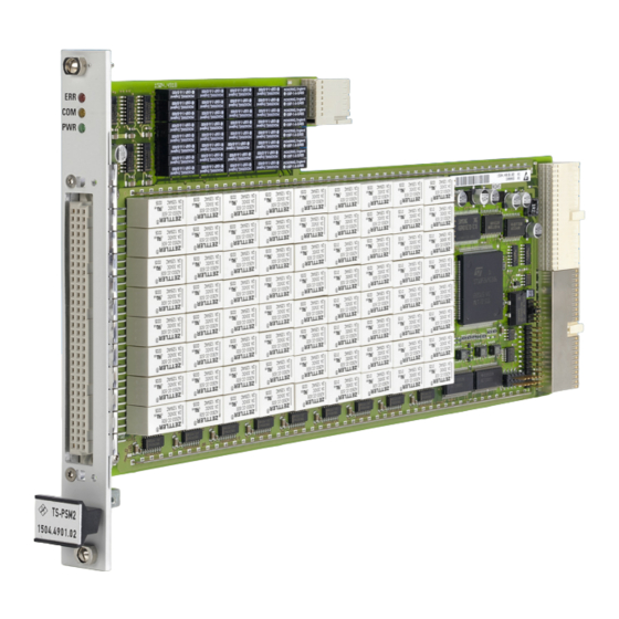
® Module tour R&S TS-PSM2 R&S TS-PSM2 4 Module tour 4.1 R&S TS-PSM2 The R&S TS-PSM2 is designed as a long plug-in module for mounting in the front of R&S TSVP base units. Figure 4-1: Overview of connectors and LEDs LEDs Chapter 4.1.1, "Status LEDs",... -
Page 15: Connectors X1 And X20
® Module tour R&S TS-PSM2 R&S TS-PRIO 4.1.2 Connectors X1 and X20 Type: Control bus Interface to connect the module to the backplane of the base units. Chapter C.1.1, "Connector X1", on page 40 and Chapter C.1.5, "Connector X20", on page 43 for a detailed description of the connectors. 4.1.3 Connector X4 and X5 Type: Clock configuration and RS232 Interfaces for internal purposes. -
Page 16: Display Elements
® Module tour R&S TS-PSM2 R&S TS-PRIO X301 X302 X303 X304 X201 X402 X401 Figure 4-2: Overview of connectors on the R&S TS-PRIO LEDs = X20 = Chapter 4.2.2, "Connector X20", on page 17 4.2.1 Display elements There are four LEDs on the rear panel of the R&S TS-PRIO module. The LEDs are connected to connectors X301 to X304 and can be connected to signals via jumpers. -
Page 17: Connector X20
® Module tour R&S TS-PSM2 R&S TS-PRIO 4.2.2 Connector X20 Type: CPCI design AB22 Interface to connect the R&S TS-PRIO to the R&S TS-PSM2. Chapter C.2.1, "Connector X20", on page 48 for a detailed description of the con- nector. User Manual 1178.2773.02 ─ 02... -
Page 18: Installing The Module
® Installing the module R&S TS-PSM2 Installing the R&S TS-PRIO 5 Installing the module 5.1 Installation R&S TS-PSM2 The R&S TS-PSM2 is a module installed on the front panel of the R&S TSVP base unit. 1. Install the module as described in the user manuals of the base units. For additional information about installing the R&S TS-PSM2 and its optional accessories, see: ●... -
Page 19: Functions
® Functions R&S TS-PSM2 R&S TS-PSM2 6 Functions 6.1 R&S TS-PSM2 (see Chapter B, "Block diagrams", on page 38) 6.1.1 Signal concept The design and construction of the Multiplex/Switch Module R&S TS-PSM2 guarantee excellent guiding of load and measurement paths. Both „Force“ channels with high cur- rents as well as „Sense“... -
Page 20: Flexibility
® Functions R&S TS-PSM2 R&S TS-PSM2 6.1.3 Flexibility The structure of the R&S TS-PSM2 in addition to the wide voltage and current range, combined with effective use extending into the lower MHz range, guarantee a high level of flexibility and a wide range of uses. Even complex yet flexible load systems with original loads and/or electronic loads can be implemented using multiple module- internal connections. -
Page 21: Compactness
® Functions R&S TS-PSM2 R&S TS-PSM2 consists of integrating project-specific additions via the side and system connector X50 (for example passive loads, terminating resistors, voltage distributors, etc.). 6.1.4 Compactness The layout of the R&S TS-PSM2 (one slot) with 112 relays offers maximum space sav- ings. - Page 22 ® Functions R&S TS-PSM2 R&S TS-PSM2 6.1.6.3 Current measurement - indirect, via shunt resistor The circuit is closed or opened through the relay. The voltage drop on the shunt resis- tor is measured with a voltmeter via the R&S analog bus. The current can be calcula- ted from the voltage and the value of the shunt.
- Page 23 ® Functions R&S TS-PSM2 R&S TS-PSM2 CH1_HI1 Local Analog Bus/ CH1_LO1 Analog Bus CH1_HI2 CH1_LO2 CH1_HI3 CH1_LO3 CH1_HI4 CH1_LO4 CH1_HI Figure 6-6: Multiplexer - test object signals 6.1.6.6 Multiplexer - CompactPCI/PXI instruments Signals of adjacent CompactPCI/PXI modules can be directed to the local multiplex bus via the side connector and a two-pin changeover contact.
- Page 24 ® Functions R&S TS-PSM2 R&S TS-PSM2 CH1_HI1 Local Analog Bus/ CH1_LO1 Analog Bus CH1_HI2 CH1_LO2 CH1_HI3 CH1_LO3 CH1_HI4 CH1_LO4 CH1_HI Side Connector Cable Figure 6-7: Multiplexer - CompactPCI/PXI instruments 6.1.6.7 Multiplexer - external components, up to 1 A Signals of external components can be directed to the local multiplexer bus via the local R&S analog bus and an optional customer-specific rear I/O module.
-
Page 25: R&S Ts-Prio
® Functions R&S TS-PSM2 R&S TS-PRIO Backplane Connector Connector External Instrument Cable Module CH1_HI1 Local Analog Bus CH1_LO1 CH1_HI2 CH1_LO2 CH1_HI3 CH1_LO3 CH1_HI4 CH1_LO4 CH1_HI Figure 6-8: Multiplexer - external components, up to 1 A 6.2 R&S TS-PRIO 6.2.1 Analog bus wiring The R&S TS-PRIO module is equipped with 8 channels wired identically as follows (shown with the example of channel 1). - Page 26 ® Functions R&S TS-PSM2 R&S TS-PRIO CH1A_COM_X20 CH1A_COM ½ K1 CH1A_NO CH1B_COM_X20 CH1B_COM ½ K1 CH1B_NO CH1_CTRL_X20 X201 SW control bit 0 Figure 6-9: Circuit diagram of channel 1 R&S TS-PRIO X201 to X207 are 10-pin connectors, of which only 8 contacts are used for one chan- nel.
-
Page 27: Wiring Of The Aux Lines
® Functions R&S TS-PSM2 R&S TS-PRIO Local analog bus R&S TS-PRIO signal LABB2 CH4A_COM_X20 LABC1 CH5A_COM_X20 LABD1 CH6A_COM_X20 LABC2 CH7A_COM_X20 LABD2 CH8A_COM_X20 The R&S TS-PSM2 software can switch the relay in the above circuit diagram via the following function. Then, the signal present at the analog bus or CHxA_COM_X20 is additionally routed to pin CHxA_NO. -
Page 28: Software
® Software R&S TS-PSM2 Software R&S TS-PSM2 7 Software 7.1 Software R&S TS-PSM2 7.1.1 Driver software A LabWindows IVI driver is available to control the Multiplex/Switch Module R&S TS- PSM2 that supports class IVI SWTCH. All additional functions of the hardware are sup- ported by specific extensions of the driver. -
Page 29: Sample Programs
® Software R&S TS-PSM2 Software R&S TS-PSM2 Figure 7-1: Softpanel R&S TS-PSM2 7.1.3 Sample programs 7.1.3.1 Programming with GTSL libraries This example connects TS-PSM2 channel 1 to different internal and external switch channels. Error handling is not considered in this sample in order to keep it easy to read. - Page 30 ® Software R&S TS-PSM2 Software R&S TS-PSM2 physical.ini ------------ [device->psm2_7] Description = "TS-PSM2, Slot 7" Type = PSM2 ResourceDesc = CAN0::0::2::7 DriverDll = rspsm2.dll DriverPrefix = rspsm2 DriverOption = "Simulate=0,RangeCheck=1" ; the analog bus pseudo device is used by the switch manager [device->abus] Type = AB...
- Page 31 ® Software R&S TS-PSM2 Software R&S TS-PSM2 int main (int argc, char *argv[]) long residSwmgr; /* resource ID for switch manager library */ short errorOccurred = 0; long errorCode = 0; char errorMessage [GTSL_ERROR_BUFFER_SIZE] = ""; /* load the physical and application configuration files */ RESMGR_Setup ( 0, "physical.ini", "Psm2Application.ini", &errorOccurred, &errorCode, errorMessage);...
- Page 32 ® Software R&S TS-PSM2 Software R&S TS-PSM2 SWMGR_DisconnectAll ( 0, residSwmgr, &errorOccurred, &errorCode, errorMessage); /* close the library */ SWMGR_Cleanup ( 0, residSwmgr, &errorOccurred, &errorCode, errorMessage); RESMGR_Cleanup ( 0, &errorOccurred, &errorCode, errorMessage); return 0; 7.1.3.2 Programming with device drivers Error handling is not considered in this sample in order to keep it easy to read.
-
Page 33: Software R&S Ts-Prio
® Software R&S TS-PSM2 Software R&S TS-PRIO /* connect local analog bus line to analog bus line on back plane */ status = rspsm2_Connect (vi, "ABa1", "LABa1"); /* connect local analog bus line to analog bus line on back plane */ status = rspsm2_Connect (vi, "ABa2", "LABa2");... -
Page 34: Maintenance, Storage And Disposal
® Maintenance, storage and disposal R&S TS-PSM2 Disposal 8 Maintenance, storage and disposal 8.1 Storage Protect the product against dust. Ensure that the environmental conditions, e.g. tem- perature range and climatic load, meet the values specified in the data sheet. 8.2 Disposal Rohde &... -
Page 35: Troubleshooting
® Troubleshooting R&S TS-PSM2 Power-on test 9 Troubleshooting If the system is not running properly, try to find the problem with the following tests. If the tests do not help to locate the problem, contact your Rohde & Schwarz service rep- resentative. -
Page 36: R&S Tsvp Self-Test
® Troubleshooting R&S TS-PSM2 Contacting customer support Power-on test for modules with a rear I/O supply module If the green LED indicates a problem with the supply voltage, check the LEDs of the corresponding rear I/O supply module separately. If the LEDs on the rear I/O module also indicate a supply voltage failure, replace the rear I/O module. -
Page 37: Annex
® Specifications R&S TS-PSM2 Annex A Specifications For an overview of technical specifications of the R&S TS-PSM2 module, refer to the corresponding product brochure / data sheet. If discrepancies exist between information in this manual and the values in the data sheet, the values in the data sheet take precedence. -
Page 38: B Block Diagrams
® Block diagrams R&S TS-PSM2 B Block diagrams Figure B-1 Figure B-2 shows the functional block diagram and the block diagram of the Multiplex/Switch Module R&S TS-PSM2. TS-PSM2 Analog Bus (AB) Analog Bus Coupling Relais Local Analog Bus (LAB) LABA1...LABD2 CHANNEL 1 CHANNEL 2 CHANNEL 3... - Page 39 ® Block diagrams R&S TS-PSM2 Figure B-2: Detailed block diagram R&S TS-PSM2 User Manual 1178.2773.02 ─ 02...
-
Page 40: C Interface Description
® Interface description R&S TS-PSM2 R&S TS-PSM2 C Interface description C.1 R&S TS-PSM2 C.1.1 Connector X1 F E D C B A Z Figure C-1: R&S TS-PSM2 Connector X1 (view: mating side) 12..14 Figure C-2: R&S TS-PSM2 Assignment of X1 User Manual 1178.2773.02 ─... -
Page 41: Connector X4
® Interface description R&S TS-PSM2 R&S TS-PSM2 C.1.2 Connector X4 Figure C-3: R&S TS-PSM2 Connector X4 (view: mating side) Table C-1: R&S TS-PSM2 assignment of x4 Signal Signal PRO_DAT_4 MAN_RST/ OSC_CLK10 PRO_CLK10 PXI_CLK10 PRO_CLK_R OSC_OE C.1.3 Connector X5 Figure C-4: R&S TS-PSM2 Connector X5 (view: mating side) Table C-2: R&S TS-PSM2 assignment of x5 Signal Signal... -
Page 42: Connector X10
® Interface description R&S TS-PSM2 R&S TS-PSM2 C.1.4 Connector X10 Figure C-5: R&S TS-PSM2 Connector X10 (view: mating side) Table C-3: R&S TS-PSM2 assignment of x10 (signals printed in bold are high power) CH1_HI1 CH1_LO1 CH1_THRU CH1_HI2 CH1_LO2 CH1_HI3 CH1_LO3 CH1_HI4 CH1_LO4 CH1_HI... -
Page 43: Connector X20
® Interface description R&S TS-PSM2 R&S TS-PSM2 CH5_LO2 CH5_HI3 CH5_LO3 CH5_HI4 CH5_LO4 CH5_HI CH5_LO CH6_HI1 CH6_LO1 CH6_THRU CH6_HI2 CH6_LO2 CH6_HI3 CH6_LO3 CH6_HI4 CH6_LO4 CH6_HI CH6_LO CH7_HI1 CH7_LO1 CH7_THRU CH7_HI2 CH7_LO2 CH7_HI3 CH7_LO3 CH7_HI4 CH7_LO4 CH7_HI CH7_LO CH8_HI1 CH8_LO1 CH8_THRU CH8_HI2 CH8_LO2 CH8_HI3 CH8_LO3... -
Page 44: Connector X30
® Interface description R&S TS-PSM2 R&S TS-PSM2 +5V (PWA) +5V (PWA) AUX1R AUX2R AUX1L AUX2L +5V (PWA) PXI_TRIG6 CAN_EN PXI_TRIG5 PXI_TRIG4 PXI_TRIG3 PXI_CLK10 PXI_TRIG2 PXI_TRIG7 PXI_TRIG0 PXI_TRIG1 +5V (PWA) LABA1 LABC1 LABB1 LABD1 LABA2 LABC2 LABB2 LABD2 RSA0 RRST# RSD0 RSDI RSA1 RSCLK... -
Page 45: Connector X40
® Interface description R&S TS-PSM2 R&S TS-PSM2 C.1.7 Connector X40 Figure C-9: R&S TS-PSM2 Connector X40 (view: mating side) Table C-5: R&S TS-PSM2 assignment of x40, version 1.x and version 2.x Signal Signal LABA1 LABC1 LABD1 LABB1 LABC2 LABA2 LABD2 LABB2 AUX2R User Manual 1178.2773.02 ─... - Page 46 ® Interface description R&S TS-PSM2 R&S TS-PSM2 Signal Signal AUX1R AUX2L AUX1L CH1_SIDECON_HI CH1_SIDECON_LO CH2_SIDECON_HI CH2_SIDECON_LO CH3_SIDECON_HI CH3_SIDECON_LO CH4_SIDECON_HI CH4_SIDECON_LO CH5_SIDECON_HI CH5_SIDECON_LO CH6_SIDECON_HI CH6_SIDECON_LO CH7_SIDECON_HI CH7_SIDECON_LO CH8_SIDECON_HI CH8_SIDECON_LO Table C-6: R&S TS-PSM2 assignment of x40, from version 3.x Signal Signal LABA1 LABA2 LABB1...
- Page 47 ® Interface description R&S TS-PSM2 R&S TS-PSM2 Signal Signal AUX2R AUX1R AUX2L AUX1L CH1_SIDECON_HI CH1_SIDECON_LO CH2_SIDECON_HI CH2_SIDECON_LO CH3_SIDECON_HI CH3_SIDECON_LO CH4_SIDECON_HI CH4_SIDECON_LO CH5_SIDECON_HI CH5_SIDECON_LO CH6_SIDECON_HI CH6_SIDECON_LO CH7_SIDECON_HI CH7_SIDECON_LO CH8_SIDECON_HI CH8_SIDECON_LO User Manual 1178.2773.02 ─ 02...
-
Page 48: Connector X50
® Interface description R&S TS-PSM2 R&S TS-PRIO C.1.8 Connector X50 Figure C-10: R&S TS-PSM2 Connector X50 (view: mating side) Table C-7: R&S TS-PSM2 assignment of x50 Signal Signal RRST/ RSCLK RSDI RSDO RSA0 RSA1 CAN_H CAN_L SYSCON_IO_0 SYSCON_IO_1 SYSCON_IO_2 SYSCON_IO_3 SYSCON_IO_4 SYSCON_IO_5 SYSCON_IO_6... - Page 49 ® Interface description R&S TS-PSM2 R&S TS-PRIO Figure C-11: R&S TS-PRIO Connector X20 Table C-8: R&S TS-PRIO assignment of connector x20 +5V_PXI_ +5V_PXI_ -12V_PXI +5V_PXI_ AUX2_X20 AUX1_X20 CAN_EN_i +5V_PXI_I +5V_PXI_I +5V_PXI_I +5V_PXI_I +5V_PXI_ CH5A_CO CH1B_CO CH1A_CO M_X20 M_X20 M_X20 CH5_CTR CH2B_CO CH1_CTR L_X20...
-
Page 50: Rear Connector X34
® Interface description R&S TS-PSM2 R&S TS-PRIO CH7_CTR CH6B_CO CH3_CTR L_X20 M_X20 L_X20 CH8A_CO CH7B_CO CH4A_CO M_X20 M_X20 M_X20 CH8_CTR CH8B_CO CH4_CTR L_X20 M_X20 L_X20 RSDO RRST# RSA0 RSCLK RSA1 RSDI +12V_PXI RCS# +5V_PXI_ C.2.2 Rear connector X34 Figure C-12: R&S TS-PRIO Connector X34 Table C-9: R&S TS-PRIO assignment of connector x34 Signal R_AUX1... -
Page 51: Jumper
® Interface description R&S TS-PSM2 R&S TS-PRIO Signal CH6A_COM CH7B_NO CH7A_NO CH7B_COM CH7A_COM CH8B_NO CH8A_NO CH8B_COM CH8A_COM C.2.3 Jumper The jumpers available on the module have been correctly configured ex works for the function described above. The delivery status is described in the following. X401 X201 X202... - Page 52 ® Interface description R&S TS-PSM2 R&S TS-PRIO X303 8-10 X304 8-10 User Manual 1178.2773.02 ─ 02...
Need help?
Do you have a question about the Multiplex/Switch Module 2 and is the answer not in the manual?
Questions and answers