
Subscribe to Our Youtube Channel
Related Manuals for Rohde & Schwarz OSP-B157W8


Summary of Contents for Rohde & Schwarz OSP-B157W8
- Page 1 ® R&S OSP‑B157W8 ® R&S OSP‑B157W8PLUS ® R&S OSP‑B157WX 8-Port Modules for Switch Units User Manual (;ÜÇí2) 1178579502...
- Page 2 ® This document describes the following optional modules for the R&S OSP switch unit family: ● ® R&S OSP-B157W8 (order number 1527.1144.02) ● ® R&S OSP-B157W8PLUS (order number 1527.1144.05) ● ® R&S OSP-B157WX (order number 1531.4909.02) Software: ● R&S ®...
-
Page 3: Table Of Contents
® ® ® Contents R&S OSP‑B157W8 R&S OSP‑B157W8PLUS R&S OSP‑B157WX Contents 1 Preface....................5 2 Documentation Overview..............9 Getting Started Manual....................9 User Manual........................9 Operating Manual of the Switch Unit................9 Help..........................9 Basic Safety Instructions................... 10 R&S OSP on the Internet.................... 10 3 Preparing for Use................. - Page 4 ® ® ® Contents R&S OSP‑B157W8 R&S OSP‑B157W8PLUS R&S OSP‑B157WX Measurement Commands..................59 Sum-Power Detector Commands................62 List of Commands.......................65 9 Maintenance..................68 Replacing the Power Supply Fuses................68 Cleaning........................69 Storing and Packing....................70 10 Troubleshooting................... 71 10.1 Status LEDs......................... 71 10.2 Resolving Network Connection Failures..............
-
Page 5: Preface
The R&S OSP is referred to as "switch unit". Integration ● The base module R&S OSP-B157W8 or R&S OSP-B157W8PLUS is (or must be) integrated in an R&S OSP150 or R&S OSP120 switch unit. ● The extension module R&S OSP-B157WX is (or must be) integrated in an R&S OSP120 switch unit (not in an R&S OSP150). - Page 6 DUT input ports of the base module, but bypassed directly to the signal analyzer. Key features of the base module R&S OSP-B157W8 The 6 GHz module R&S OSP-B157W8 with up to 8 channels is based on a printed RF switch board in solid-state relay (SSR) architecture. It allows flexible operation of the connected DUT (up to 8 ports) and measurement instruments.
- Page 7 OSP‑B157WX ● Additional step attenuator R2 for an extended attenuation range, see Figure 4-3 Each of the 8 configurable channels in the R&S OSP-B157W8 and R&S OSP- B157W8PLUS has the following integrated semiconductor components: ● An individually programmable attenuator ●...
- Page 8 ® ® ® Preface R&S OSP‑B157W8 R&S OSP‑B157W8PLUS R&S OSP‑B157WX Screenshots Sample screenshots in this documentation are used to illustrate as much as possible of the functions provided by the modules and of potential interdependencies between parameters. Note that: ● The values in these screenshots do not necessarily represent realistic application situations.
-
Page 9: Documentation Overview
OSP‑B157W8PLUS R&S OSP‑B157WX Help 2 Documentation Overview This section provides an overview of the R&S OSP-B157W8, R&S OSP-B157W8PLUS and R&S OSP-B157WX user documentation. Unless specified otherwise, you find the documents on the R&S OSP product page at: www.rohde-schwarz.com/manual/osp 2.1 Getting Started Manual Introduces the modules and describes how to set up and start working with them. -
Page 10: Basic Safety Instructions
® ® ® Documentation Overview R&S OSP‑B157W8 R&S OSP‑B157W8PLUS R&S OSP‑B157WX R&S OSP on the Internet various FCC and ETSI standards. Examples are FCC 15.407, ETSI EN 300 328 or ETSI EN 301 893. The software, which requires a license, is available at www.rohde-schwarz.com/soft- ware/emc32. - Page 11 ® ® ® Documentation Overview R&S OSP‑B157W8 R&S OSP‑B157W8PLUS R&S OSP‑B157WX R&S OSP on the Internet 2.6.2 Application Notes Application notes and application cards deal with special applications or background information on particular topics. See www.rohde-schwarz.com/application/osp. 2.6.3 Drivers Up-to-date instrument drivers are available for download. See www.rohde-schwarz.com/driver/osp.
-
Page 12: Preparing For Use
Module. 3.2 Mounting the Base Module Mounting the base module R&S OSP-B157W8 or R&S OSP-B157W8PLUS into an R&S OSP150 or R&S OSP120 switch unit requires the space of two slots: rear slots A12 and A13 together with front slots A12F and A13F. Typically, the rear slot A11 remains free, but optionally it can remain occupied by a single-slot module (not opera- tional). - Page 13 Removing an existing (old) R&S OSP-B157 module If you want to install the R&S OSP-B157W8 or R&S OSP-B157W8PLUS in a switch unit, which is occupied by an existing module (for example R&S OSP-B157), first remove the existing module.
- Page 14 ® ® ® Preparing for Use R&S OSP‑B157W8 R&S OSP‑B157W8PLUS R&S OSP‑B157WX Mounting the Base Module 2. Unplug the power supply cable. 3. Disconnect all other cables, too. 4. If the switch unit holds any modules, remove these modules and their ribbon cables, except for a module in the rear slot A11.
- Page 15 ® ® ® Preparing for Use R&S OSP‑B157W8 R&S OSP‑B157W8PLUS R&S OSP‑B157WX Mounting the Base Module Figure 3-1: Guide cage for holding the module in the switch unit 1 = 2 holes for accessing 2 screw hole positions below 2 = Protruding flange 3 = 3 screw holes 4 = Guiding structure elements, into which you slide the module in step 26...
- Page 16 ® ® ® Preparing for Use R&S OSP‑B157W8 R&S OSP‑B157W8PLUS R&S OSP‑B157WX Mounting the Base Module 28. Insert the single end of cable W20 (with the 12-pole connector) through the open front panel of the switch unit while passing the guide cage on its right-hand side.
-
Page 17: Mounting The Extension Module
® ® ® Preparing for Use R&S OSP‑B157W8 R&S OSP‑B157W8PLUS R&S OSP‑B157WX Mounting the Extension Module 11 = Cable holder for fixing cable W20 12 = Detail: identifying the connector for the short end (9) of cable W20 13 = Detail: view from the front of the switch unit (front panel not shown) through the empty guide cage towards the rear panel 33. - Page 18 ® ® ® Preparing for Use R&S OSP‑B157W8 R&S OSP‑B157W8PLUS R&S OSP‑B157WX Mounting the Extension Module Risk of injuries When removing the rear feet, the switch unit can slip out of its casing. To avoid the risk of personal injuries and any damage, put the switch unit onto its front handles before removing the rear feet and taking off the casing.
- Page 19 ® ® ® Preparing for Use R&S OSP‑B157W8 R&S OSP‑B157W8PLUS R&S OSP‑B157WX Mounting the Extension Module 8. If you have removed one or two modules from rear slots A12 or A13, close the open slots with blind plates, using the same screws that fixed the modules. 9.
- Page 20 ® ® ® Preparing for Use R&S OSP‑B157W8 R&S OSP‑B157W8PLUS R&S OSP‑B157WX Mounting the Extension Module 1 = Adapter plate with 11 threaded insert nuts (dark gray) and 12 screws (yellow) that fix the adapter plate to the base plate of the switch unit 2 = Ground plate of the module, here in an isolated presentation for better view of the 11 screws (yel- low) that fix the module to the adapter plate 3 = Top view of the complete module with the same 11 screws highlighted as in the isolated presenta-...
-
Page 21: Installing Or Updating The Firmware
34. Reconnect the power cable to the unit. 3.4 Installing or Updating the Firmware For installing or updating the firmware of the R&S OSP-B157W8 or R&S OSP- B157W8PLUS, use the R&S WMS32 software package in the R&S RF Test Suite. -
Page 22: Putting Into Operation
Proceed as follows: 1. Click "Self Check". 2. Select the "R&S OSP-B157W8" or "R&S OSP-B157W8PLUS" entry in the device list of the "Self Check" dialog and click "Test device". 3. In the "Firmware Update" tab of the next dialog, click "Select Firmware File" and browse to the correct file. - Page 23 ® ® ® Preparing for Use R&S OSP‑B157W8 R&S OSP‑B157W8PLUS R&S OSP‑B157WX Putting into Operation Risk of injury when stacking instruments A stack of instruments can tilt over and cause injury if not stacked correctly. Further- more, the instruments at the bottom of the stack can be damaged due to the load imposed by the instruments on top.
- Page 24 R&S OSP. This manual also contains valuable information on the switch unit's setup, on remote operation, on working with the operating system, and much more. Unlike all other modules for R&S OSP switch units, the R&S OSP-B157W8 and R&S OSP-B157W8PLUS are not equipped with on-board memory to store the switch- ing configuration of the module's signal paths.
- Page 25 ® ® ® Preparing for Use R&S OSP‑B157W8 R&S OSP‑B157W8PLUS R&S OSP‑B157WX Putting into Operation Use RF connector adapters as port savers SMA and K-type RF connectors have a limited lifetime. It is typically limited to 500 con- nector mating cycles, due to normal wear. After this number of mating cycles, the con- nectors must be replaced.
-
Page 26: Tour Of The Base Module
R&S OSP switch units (see chapter on R&S EMC32 software). On the front panel, the R&S OSP-B157W8 or R&S OSP-B157W8PLUS has the con- nectors for up to eight DUT channels and for the test instruments: Figure 4-1: R&S OSP-B157W8 mounted in R&S OSP150 (front panel view) Less frequently used connectors are on the rear panel: Figure 4-2: R&S OSP-B157W8 mounted in R&S OSP150 (rear panel view) - Page 27 Tour of the Base Module R&S OSP‑B157W8 R&S OSP‑B157W8PLUS R&S OSP‑B157WX Figure 4-3: Circuit diagram of the R&S OSP-B157W8 and R&S OSP-B157W8PLUS RF board Orange, right = Front DUT and instrument ports Orange, left = Instrument or trigger ports, and data acquisition board...
-
Page 28: Connecting Devices To The Base Module
® ® ® Tour of the Base Module R&S OSP‑B157W8 R&S OSP‑B157W8PLUS R&S OSP‑B157WX Connecting Devices to the Base Module The exact behavior of the module is test-case-specific and depends on the applicable test standard. This flexibility allows setting up and handling complex test and measure- ment sequences with the connected devices. - Page 29 Trig 2 Trigger output Ch2 Analog BNC High: 3.3 V, low: 0 V If you use the base module R&S OSP-B157W8 or R&S OSP-B157W8PLUS in combi- nation with the extension module R&S OSP-B157WX, make the following changes to the connections listed above: ●...
-
Page 30: Tour Of The Extension Module
For controlling the R&S OSP-B157WX, use the RJ45 LAN connector on the rear panel of the switch unit. Hence, for controlling a combination of both the R&S OSP-B157W8 or R&S OSP- B157W8PLUS and R&S OSP-B157WX in an R&S TS8997 test system, use two LAN cables to connect the modules to the test systems' Ethernet switch. -
Page 31: Connecting Devices And A Base Module To The Extension Module
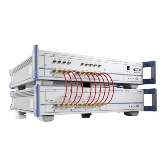
With this RF circuitry, the R&S OSP-B157WX is operated in the test system as follows: ● Incoming signals on each DUT channel are forwarded to the connected DUT input of the base module R&S OSP-B157W8 (supporting up to 6 GHz) respectively R&S OSP-B157W8PLUS (supporting up to 7.5 GHz). ●... - Page 32 6. Connect the port [RxOUT] of the R&S OSP-B157WX to the port [Rx] of the R&S OSP-B157W8 or R&S OSP-B157W8PLUS. Figure 5-4: Connected modules, upper = R&S OSP-B157WX, lower = R&S OSP-B157W8 or R&S OSP-B157W8PLUS User Manual 1178.5795.02 ─ 03...
- Page 33 Note that "RxOUT" is - in spite of its name - an input port for signals coming from the "Rx" port of the R&S OSP-B157W8 or R&S OSP-B157W8PLUS base module. The label "RxOUT" was chosen due to the connection with the Rx output port of the base module.
-
Page 34: Operating The Modules
SCPI Commands....................40 6.1 Calibration The modules R&S OSP-B157W8 or R&S OSP-B157W8PLUS and R&S OSP-B157WX are delivered with a factory calibration, conforming to the standards of the German national accreditation body. The calibration data is saved in the modules. User Manual 1178.5795.02 ─ 03... -
Page 35: Configuring Devices And Signal Paths
If, instead of factory mounting, the modules are mounted by the Rohde & Schwarz ser- vice, the calibration is preserved. For a later recalibration, including the power detectors in the R&S OSP-B157W8 or R&S OSP-B157W8PLUS, we recommend that you send your switch unit (with the module) to the Rohde &... - Page 36 ® ® ® Operating the Modules R&S OSP‑B157W8 R&S OSP‑B157W8PLUS R&S OSP‑B157WX Configuring Devices and Signal Paths ● Have the address for each of your devices available. (The type of address depends on the device's interface and its protocol, which can be IP, GPIB or USB / RS232.) Obtaining valid IP addresses If your network does not support DHCP or if you choose to disable dynamic TCP/IP configuration, you must assign valid address information before connecting the instru-...
- Page 37 R&S OSP‑B157W8 R&S OSP‑B157W8PLUS R&S OSP‑B157WX Configuring Devices and Signal Paths The R&S TS8997 can now be used with the R&S OSP-B157W8 or R&S OSP- B157W8PLUS and R&S OSP-B157WX, see Chapter 6.3, "Operation Overview", on page 39. Use the R&S OSP Panel software to register the R&S OSP as described in the...
- Page 38 ® ® ® Operating the Modules R&S OSP‑B157W8 R&S OSP‑B157W8PLUS R&S OSP‑B157WX Configuring Devices and Signal Paths 5. In the dialog that comes up, select the "Shortcut" tab. 6. Enter a space and the name of the new profile (for example "Profile") as an address parameter at the end of the "Target"...
-
Page 39: Operation Overview
Operating the Extension Module................40 6.3.1 Operating the Base Module Use the R&S WMS32 software to control the base module R&S OSP-B157W8 or R&S OSP-B157W8PLUS. Manual operation of the module or control via the R&S OSP Panel software tool is not possible. -
Page 40: Scpi Commands
® ® ® Operating the Modules R&S OSP‑B157W8 R&S OSP‑B157W8PLUS R&S OSP‑B157WX SCPI Commands 6.3.2 Operating the Extension Module Use the R&S WMS32 software to control the frequency extension module R&S OSP- B157WX. Manual operation of the module or remote control via the R&S OSP Panel software tool is not possible. -
Page 41: Measurements
The modules serve for switching the signal paths between a DUT and the required test instruments. Also, the signals can be conditioned and their power levels can be measured in the R&S OSP-B157W8 or R&S OSP-B157W8PLUS. This func- tionality is used in a broad range of tests. -
Page 42: Remote Control Commands
These commands are described in the service manual (1178.6504.02) of the R&S OSP-B157W8, R&S OSP-B157W8PLUS and R&S OSP-B157WX. For direct SCPI communication with the modules, proceed as follows: ● If you want to communicate with the module R&S OSP-B157W8 or R&S OSP- B157W8PLUS: 1. Connect the module's LAN connector (Figure 4-2) to your control computer or to your local area network. -
Page 43: Common Commands
6. If the command is a query, click the "Read" button. For the R&S OSP-B157WX, only use SCPI commands from the operating manual the R&S OSP. The SCPI commands available for the R&S OSP-B157W8 or R&S OSP- B157W8PLUS (not R&S OSP-B157WX) are described in the following chapters. ● Common Commands.................... - Page 44 ® ® ® Remote Control Commands R&S OSP‑B157W8 R&S OSP‑B157W8PLUS R&S OSP‑B157WX Common Commands ● EVENt part of the QUEStionable and the OPERation register ● Error/event queue The command clears the output buffer. It does not alter the ENABle and TRANsition parts of the registers.
- Page 45 ® ® ® Remote Control Commands R&S OSP‑B157W8 R&S OSP‑B157W8PLUS R&S OSP‑B157WX Common Commands *OPC Operation complete, sets bit 0 in the event status register, when all preceding com- mands have been executed. This bit can be used to initiate a service request. The query writes a "1"...
- Page 46 ® ® ® Remote Control Commands R&S OSP‑B157W8 R&S OSP‑B157W8PLUS R&S OSP‑B157WX Common Commands Parameters: <Number> Identifies the intermediate memory. *RST Reset, sets the instrument to a defined default status. Same as SYST:PRES. Usage: Setting only *SAV <Number> Save, stores the current instrument settings in an intermediate memory. The settings can be recalled using the command with the associated number.
-
Page 47: General Setting Commands
® ® ® Remote Control Commands R&S OSP‑B157W8 R&S OSP‑B157W8PLUS R&S OSP‑B157WX General Setting Commands *TST? Self-test query, initiates a self-test of the instrument and returns an error code. Parameters: <ErrorCode> No errors occurred. An error occurred. Usage: Query only *WAI Wait to continue, prevents servicing of the subsequent commands until all preceding commands have been executed and all signals have settled. - Page 48 ® ® ® Remote Control Commands R&S OSP‑B157W8 R&S OSP‑B157W8PLUS R&S OSP‑B157WX General Setting Commands SYSTem:COMMunicate:NET:[COMMon:]HOSTname <hostname> Specifies the network name. Parameters: <hostname> Allows an arbitrary text string as the hostname. SYSTem:COMMunicate:NET:IPADdress <ipaddress> is disabled, this value sets the static IP address. DHCP Parameters: <ipaddress>...
-
Page 49: Configuration Setting Commands
® ® ® Remote Control Commands R&S OSP‑B157W8 R&S OSP‑B157W8PLUS R&S OSP‑B157WX Configuration Setting Commands Suffix: {1|2} You can specify two DNS server addresses for IP address matching. The suffix determines, whether the command sets the or 2 DNS address. Parameters: <dns>... - Page 50 ® ® ® Remote Control Commands R&S OSP‑B157W8 R&S OSP‑B157W8PLUS R&S OSP‑B157WX Configuration Setting Commands ......................52 CONFigure:CLOCk ..................53 CONFigure:TRIGger:INPut{m}? ..................53 CONFigure:TRIGger:OUTPut{m} CONFigure:PORT{n}:ATTenuator <numeric_value> Sets the signal path from the selected port to the attenuator. Suffix: 1 to 8 Sets the port number.
- Page 51 ® ® ® Remote Control Commands R&S OSP‑B157W8 R&S OSP‑B157W8PLUS R&S OSP‑B157WX Configuration Setting Commands Signal path from the signal generator to the analyzer. Signal path from the signal generator to the antenna. SELF Signal path from the signal generator to the self-test. CONFigure:GENerator ON | OFF Enables or disables the signal generator input, or queries the signal generator input state.
- Page 52 The available range of attenuation levels depends on the base unit version (.02 or .05). Parameters: <attenuation_level> Range: 0 to 31.75 for the R&S OSP-B157W8 (version .02), 0 to 63.50 for the R&S OSP-B157W8PLUS (.05) Default unit: dB CONFigure:CLOCk <clockselect>...
-
Page 53: Measurement Setting Commands
® ® ® Remote Control Commands R&S OSP‑B157W8 R&S OSP‑B157W8PLUS R&S OSP‑B157WX Measurement Setting Commands CEXTernal Enables using an external clock. CONFigure:TRIGger:INPut{m}? Returns the state of the trigger input on the selected trigger channel. Suffix: 1 to 4 Selects the channel number of the input trigger. Example: If the query CONF:TRIG:INP1? returns "0", the trigger has not been released and the input level at trigger port 1 is 0 V (or at... - Page 54 ® ® ® Remote Control Commands R&S OSP‑B157W8 R&S OSP‑B157W8PLUS R&S OSP‑B157WX Measurement Setting Commands ..................55 [SENSe{1..8}:][SAMPling:]MODE ..................56 [SENSe{1..8}:][SAMPling:]COUNt ................. 56 [SENSe{1..8}:][SAMPling:]PRECount ................56 [SENSe{1..8}:][SAMPling:]OPERation ..................56 [SENSe{1..8}:]TRIGger{1..4}:SET ....................57 [SENSe{1..8}:]STATus? ..................57 [SENSe{1..8}:]BURSt:SEARchlevel ................58 [SENSe{1..8}:]CORRection:ATTenuation ................... 58 [SENSe{1..8}:]CORRection:BFGain ..................
- Page 55 ® ® ® Remote Control Commands R&S OSP‑B157W8 R&S OSP‑B157W8PLUS R&S OSP‑B157WX Measurement Setting Commands Parameters: <time> Range: 1.0e-3 to 100.0 *RST: Default unit: s Usage: Query only [SENSe{1..8}:][SAMPling:]RATE? <sampling_rate> Specifies the sampling rate for the selected sensor. Parameters: <sampling_rate> Range: 10e6 to 10e7 *RST:...
- Page 56 ® ® ® Remote Control Commands R&S OSP‑B157W8 R&S OSP‑B157W8PLUS R&S OSP‑B157WX Measurement Setting Commands Stores the maximum value of all samples between two saving times (during the divider interval). MEAN Stores the arithmetic mean value of all samples between two saving times (during the divider interval).
- Page 57 ® ® ® Remote Control Commands R&S OSP‑B157W8 R&S OSP‑B157W8PLUS R&S OSP‑B157WX Measurement Setting Commands Suffix: {1..4} Selects the trigger input port, see Figure 4-2. If not selected, the default port is trigger 1. Parameters: <trigset> This parameter set is a group of three boolean decisions, for example "1,1,0"...
- Page 58 ® ® ® Remote Control Commands R&S OSP‑B157W8 R&S OSP‑B157W8PLUS R&S OSP‑B157WX Measurement Setting Commands (For the sum-power detector, see SUMPowerdetector:BURSt:SEARchlevel.) Parameters: <searchlevel> Specifies the numeric value of the threshold level. [W | DBM] Specifies the unit for the threshold level: "W" = watts, "DBM" = We recommend using "DBM", which sets the threshold level in relation (dB) to the highest value in the measurement.
-
Page 59: Measurement Commands
® ® ® Remote Control Commands R&S OSP‑B157W8 R&S OSP‑B157W8PLUS R&S OSP‑B157WX Measurement Commands Parameters: <frequency> Range: 0.0 to 110.0e9 *RST: 1.0e9 Default unit: Hz Inspite of the available range setting (0 Hz to 110 GHz), the calibration effectively limits the range to within 120 MHz to 6 GHz. - Page 60 ® ® ® Remote Control Commands R&S OSP‑B157W8 R&S OSP‑B157W8PLUS R&S OSP‑B157WX Measurement Commands INITiate[:IMMediate] Starts a measurement for all sensors that are activated by [SENS{1..8}:]MEAS. With the optional addition of :IMM (equivalent to *TRG), the measurement starts imme- diately. Without :IMM, the measurement starts upon a trigger event, if a trigger is activated by [SENS{1..8}:]TRIG{1..4}:SET.
- Page 61 ® ® ® Remote Control Commands R&S OSP‑B157W8 R&S OSP‑B157W8PLUS R&S OSP‑B157WX Measurement Commands Note: Since the DUTs are "load based", hence the individual durations of the bursts depend on the actual data transfer, calculating the duty cycle requires a statistical eval- uation of a number of bursts that is sufficient to do statistics.
-
Page 62: Sum-Power Detector Commands
® ® ® Remote Control Commands R&S OSP‑B157W8 R&S OSP‑B157W8PLUS R&S OSP‑B157WX Sum-Power Detector Commands The values are returned in dBm, hence with correction factors (as opposed to the data in RAW:MIN). Usage: Query only [SENSe{1..8}:]TRACe:MAX? Returns the maximum level result of the recorded trace. The values are returned in dBm, hence with correction factors (as opposed to the data in RAW:MAX). -
Page 63: Sumpowerdetector:status
® ® ® Remote Control Commands R&S OSP‑B157W8 R&S OSP‑B157W8PLUS R&S OSP‑B157WX Sum-Power Detector Commands SUMPowerdetector:STATus? Returns the status message of the sum-power sensor sampling. Parameters: <status_message> ERRor The sum-power sensor is in error mode. IDLE The sum-power sensor is idle and ready for the next measure- ment. -
Page 64: Sumpowerdetector:burst:count
® ® ® Remote Control Commands R&S OSP‑B157W8 R&S OSP‑B157W8PLUS R&S OSP‑B157WX Sum-Power Detector Commands SUMPowerdetector:BURSt:COUNt? Returns the number of detected bursts. Usage: Query only SUMPowerdetector:BURSt:LEVel? Returns an array with the detected time-domain power (TDP) levels of each burst (hence, one value per burst, while typically there may be hundreds or thousands of bursts in one measurement). -
Page 65: List Of Commands
® ® ® Remote Control Commands R&S OSP‑B157W8 R&S OSP‑B157W8PLUS R&S OSP‑B157WX List of Commands [W | DBM] Specifies the unit for the threshold level: "W" = watts, "DBM" = We recommend using "DBM", which sets the threshold level in relation (dB) to the highest value in the sum-power measure- ment. - Page 66 ® ® ® Remote Control Commands R&S OSP‑B157W8 R&S OSP‑B157W8PLUS R&S OSP‑B157WX List of Commands [SENSe{1..8}:]MU?............................61 [SENSe{1..8}:]RAW:DATA?..........................61 [SENSe{1..8}:]RAW:MAX?..........................61 [SENSe{1..8}:]RAW:MIN?..........................61 [SENSe{1..8}:]RMS?............................61 [SENSe{1..8}:]STATus?........................... 57 [SENSe{1..8}:]SUMState?..........................54 [SENSe{1..8}:]TRACe:DATA?..........................61 [SENSe{1..8}:]TRACe:MAX?........................... 62 [SENSe{1..8}:]TRACe:MIN?..........................61 [SENSe{1..8}:]TRIGger{1..4}:SET........................56 [SENSe{1..8}:]VIDeo:MAX..........................59 [SENSe{1..8}:]VIDeo:MIN..........................59 *CLS.................................43 *ESE................................44 *ESR?................................44 *IDN?................................
- Page 67 ® ® ® Remote Control Commands R&S OSP‑B157W8 R&S OSP‑B157W8PLUS R&S OSP‑B157WX List of Commands SUMPowerdetector:BURSt:STARttime?......................64 SUMPowerdetector:DCYCle?..........................65 SUMPowerdetector:INITiate[:IMMediate]......................62 SUMPowerdetector:MU?..........................65 SUMPowerdetector:STATus?.......................... 63 SUMPowerdetector:TRACe:DATA?.........................63 SUMPowerdetector:TRACe:MAX?........................63 SUMPowerdetector:TRACe:MIN?........................63 SUMPowerdetector:TRACe:RMS?........................63 SYSTem:COMMunicate:NET:[COMMon:]DNS{1|2}..................48 SYSTem:COMMunicate:NET:[COMMon:]DOMain...................48 SYSTem:COMMunicate:NET:[COMMon:]HOSTname..................48 SYSTem:COMMunicate:NET:DHCP........................ 47 SYSTem:COMMunicate:NET:GATeway......................48 SYSTem:COMMunicate:NET:IPADdress......................48 SYSTem:COMMunicate:NET:IPADdress:INFO?....................48 SYSTem:COMMunicate:NET:RESet........................49 SYSTem:COMMunicate:NET:RESTart......................49 SYSTem:COMMunicate:NET:STATus?......................49...
-
Page 68: Maintenance
Due to normal wear, the SMA and K-type RF connectors of the modules have a limited lifetime of typically 500 connector mating cycles. If these connectors are worn, replace them. For the hard-to-replace DUT ports of the base module R&S OSP-B157W8 or R&S OSP-B157W8PLUS, we recommend that you Use RF connector adapters as port savers. -
Page 69: Cleaning
® ® ® Maintenance R&S OSP‑B157W8 R&S OSP‑B157W8PLUS R&S OSP‑B157WX Cleaning 6. Insert the new fuses. 7. Push the fuse holder back into its slot. 8. Close the lid. 9. Reconnect the power cable. 9.2 Cleaning Risk of electric shock If moisture enters the casing, for example if you clean the instrument using a moist cloth, contact with the instrument can lead to electric shock. -
Page 70: Storing And Packing
® ® ® Maintenance R&S OSP‑B157W8 R&S OSP‑B157W8PLUS R&S OSP‑B157WX Storing and Packing 9.3 Storing and Packing The storage temperature range of the instrument is given in the data sheet. If the instrument is to be stored for a longer period of time, it must be protected against dust. Repack the instrument as it was originally packed when transporting or shipping. -
Page 71: Troubleshooting
® ® ® Troubleshooting R&S OSP‑B157W8 R&S OSP‑B157W8PLUS R&S OSP‑B157WX Resolving Network Connection Failures 10 Troubleshooting 10.1 Status LEDs The front panel of the base module has 2 LEDs. labeled "Power" and "Ready". The "Power" LED can show the following states: ●... - Page 72 ® ® ® Troubleshooting R&S OSP‑B157W8 R&S OSP‑B157W8PLUS R&S OSP‑B157WX Resolving Network Connection Failures Risk of network failure Consult your network administrator before performing the following tasks: ● Connecting the instrument to the network ● Configuring the network ● Changing IP addresses ●...
-
Page 73: Glossary: Abbreviations
® ® ® Glossary: Abbreviations R&S OSP‑B157W8 R&S OSP‑B157W8PLUS R&S OSP‑B157WX Glossary: Abbreviations Symbols 3GPP: 3 Generation Partnership Project, a telecommunication industry consortium BER: Bit error rate, the number of bit errors divided by the total number of transferred bits C: Common terminal of a relay (see NC and NO) CTIA: A nonprofit wireless communications industry organization in the United States, formerly known as Cellular Telecommunications Industry Association... - Page 74 ® ® ® Glossary: Abbreviations R&S OSP‑B157W8 R&S OSP‑B157W8PLUS R&S OSP‑B157WX ERP: Effective radiated power FCC: Federal Communications Commission, a US government agency for telecommu- nications regulation LAN: Local area network within a limited space, such as an office building. LAN con- nects computers or electronic equipment with processing capability, using network media technologies such as Ethernet (over electric or fiber-optic cables) or wireless LAN (Wi-Fi).
- Page 75 ® ® ® Glossary: Abbreviations R&S OSP‑B157W8 R&S OSP‑B157W8PLUS R&S OSP‑B157WX SMA connector: Sub-Miniature Assembly, a coaxial RF connector, version A (stan- dard) SNR: Signal-to-noise ratio is the ratio of the level of a desired signal to the level of background noise (measured in quantities of power).
-
Page 76: Index
40 GHz ................7 R&S OSP-B157WX ............7 Adapters (connector) ............25 Airflow ................24 R&S OSP-B157W8 / R&S OSP-B157W8PLUS ..26 Application notes ............... 11 R&S OSP-B157WX ............ 30 Attenuation, extended range ..........6 LEDs, power and ready ............. 71 Level (input power) limit .......... - Page 77 Remote control commands ......... 40, 42 Removing Existing module R&S OSP-B157 ......13, 18 RF board R&S OSP-B157W8 / R&S OSP-B157W8PLUS ..27 R&S OSP-B157WX ............ 31 RF connectors ..............25 Safety instructions ............. 10 SCPI commands ............40, 42 Screenshots ................
Need help?
Do you have a question about the OSP-B157W8 and is the answer not in the manual?
Questions and answers