Table of Contents
Advertisement
Quick Links
Advertisement
Table of Contents

Related Manuals for Rohde & Schwarz TS-PMB


Summary of Contents for Rohde & Schwarz TS-PMB
- Page 1 ® R&S TS-PMB Matrix Module B User Manual (;ÃÂQ<) 1153523312 Version 06...
- Page 2 Rohde & Schwarz GmbH & Co. KG. Trade names are trademarks of the owners. ® 1153.5233.12 | Version 06 | R&S TS-PMB ® The following abbreviations are used throughout this manual: R&S TS-PMB is abbreviated as R&S TS-PMB.
-
Page 3: Table Of Contents
User manuals.........................9 System manual......................10 Service manual......................10 Printed safety instructions..................10 Brochures and specifications..................10 Release notes and open source acknowledgment..........10 3 Welcome to the R&S TS-PMB............. 11 4 Module tour...................12 Status LEDs......................... 12 Connectors X1 and X20....................12 Connector X10......................13 Connector X30......................13 5 Installing the module................ - Page 4 ® Contents R&S TS-PMB Disposal........................20 9 Troubleshooting................... 21 LED test........................21 Power-on test......................21 R&S TSVP self-test..................... 22 Contacting customer support..................22 Annex....................23 A Specifications..................23 B Block diagram..................24 C Interface description................26 Connector X10......................26 Connector X20......................27 Connector X1.......................28 Connector X30......................30...
-
Page 5: Safety Information (Multilingual)
® Safety information (multilingual) R&S TS-PMB 1 Safety information (multilingual) This option or accessory is designed for a specific Rohde & Schwarz product. Multilin- gual safety information is delivered with the product. Follow the provided installation instructions. Esta opción o este accesorio están diseñados para un producto Rohde & Schwarz concreto. - Page 6 ® Safety information (multilingual) R&S TS-PMB See valik või lisaseade on mõeldud konkreetsele Rohde & Schwarz tootele. Tootega on kaasas mitmekeelne ohutusteave. Järgige kaasasolevaid paigaldusjuhiseid. Šī opcija vai piederums ir izstrādāts īpaši Rohde & Schwarz produktam. Produktam pievienota drošības informācija vairākās valodās. Ievērojiet sniegtos uzstādīšanas nor- ādījumus.
- Page 7 ® Safety information (multilingual) R&S TS-PMB Ova opcija ili pribor je dizajniran za određeni Rohde & Schwarz proizvod. Proizvodu su priložene sigurnosne informacije na više jezika. Slijedite priložena uputstva za instala- ciju. Ova opcija ili dodatni pribor je projektovan za određeni Rohde & Schwarz proiz- vod.
- Page 8 ® Safety information (multilingual) R&S TS-PMB Tùy chọn hoặc phụ kiện này dành riêng cho một sản phẩm Rohde & Schwarz cụ thể. Thông tin an toàn đa ngôn ngữ được cung cấp kèm theo sản phẩm. Thực hiện theo hướng dẫn lắp đặt kèm theo.
-
Page 9: Documentation Overview
® Documentation overview R&S TS-PMB User manuals 2 Documentation overview This section provides an overview of the R&S TSVP (test system versatile platform) user documentation. All documents are delivered with the Generic Test Software Library ("R&S GTSL") installation package. After installing the software, you can open all the documentation from the Windows "Start"... -
Page 10: System Manual
® Documentation overview R&S TS-PMB Release notes and open source acknowledgment Generic Test Software Library 2.3 System manual Describes the complete R&S TSVP (test system versatile platform) as a whole, includ- ing the combined use of R&S CompactTSVP and R&S PowerTSVP, plug-in modules and generic test software. -
Page 11: Welcome To The R&S Ts-Pmb
This can be done locally or using the analog bus. The R&S TS-PMB is intended for the use in the R&S TSVP base units. Typical product test applications are in the fields of communications, automotive elec- tronics and general industrial electronics, especially for analog in-circuit testing with a large number of channels. -
Page 12: Module Tour
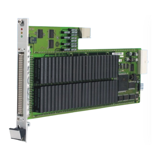
R&S TS-PMB Connectors X1 and X20 4 Module tour The R&S TS-PMB is designed as a long plug-in board for front mounting in the R&S TSVP base unit. Figure 4-1: Overview of connectors and other elements LEDs = Chapter 4.1, "Status LEDs",... -
Page 13: Connector X10
® Module tour R&S TS-PMB Connector X30 Chapter C.3, "Connector X1", on page 28 and Chapter C.2, "Connector X20", on page 27 for a detailed description of the connectors. 4.3 Connector X10 Interface to connect test objects and UUTs to the module. -
Page 14: Installing The Module
TS-PMB 5 Installing the module The R&S TS-PMB is a module installed on the front panel of the base unit. 1. Install the module as described in the user manuals of the base units. 2. WARNING! Risk of electric shock. The test environment, e.g the UUT or additional power supplies, can supply high voltages to the instruments. -
Page 15: Functions
24 for details. 6.2 Scalability The R&S TS-PMB has two switching matrices (4 x 45). These can also be configured as 8 buses x 45 pins with external connection or 4 buses x 90 pins, e.g. using plug-in module R&S TS-PSAM via the analog bus (see... -
Page 16: Interfaces
The R&S TS-PMB is controlled via CAN interface (Controller Area Network). 6.6 Power supply The R&S TS-PMB is operated with a voltage of 5 V. The power supply is provided through connector X20 for Versions V1.x and V2.x. In version V3.x or higher (first deliv- ery in 2004), the power supply is provided via connector X20 or connector X1. -
Page 17: Software
7 Software 7.1 Driver software A LabWindows CVI driver is provided for the R&S TS-PMB . This driver satisfies the IVI Switch specification. The driver is part of the ROHDE & SCHWARZ GTSL software. All the functions of the driver are described fully in the on-line help. -
Page 18: Ts-Pmb Program Example
TS-PMB program example Figure 7-1: Softpanel R&S TS-PMB (example) 7.3 TS-PMB program example Connection between ABa1 and ABb1 with TS-PMB in Slot 12 The coding rules of a GTSL software like allocating and locking the resource, or error handling are not considered in this example. - Page 19 ® Software R&S TS-PMB TS-PMB program example main() Creates a new IVI instrument driver and optionally sets the initial state of the session attributes "CAN0::0::1::12": CAN board 0, Bus Controller 0, Frame 1, Slot 12 s_status = rspmb_InitWithOptions ("CAN0::0::1::12", VI_TRUE, VI_TRUE, "", & handle);...
-
Page 20: Maintenance, Storage And Disposal
® Maintenance, storage and disposal R&S TS-PMB Disposal 8 Maintenance, storage and disposal 8.1 Storage Protect the product against dust. Ensure that the environmental conditions, e.g. tem- perature range and climatic load, meet the values specified in the data sheet. -
Page 21: Troubleshooting
® Troubleshooting R&S TS-PMB Power-on test 9 Troubleshooting If the system is not running properly, try to find the problem with the following tests. If the tests do not help to locate the problem, contact your Rohde & Schwarz service rep- resentative. -
Page 22: R&S Tsvp Self-Test
® Troubleshooting R&S TS-PMB Contacting customer support Power-on test for modules with a rear I/O supply module If the green LED indicates a problem with the supply voltage, check the LEDs of the corresponding rear I/O supply module separately. If the LEDs on the rear I/O module also indicate a supply voltage failure, replace the rear I/O module. -
Page 23: Annex
TS-PMB Annex A Specifications For an overview of technical specifications of the R&S TS-PMB module, refer to the corresponding product brochure / data sheet. If discrepancies exist between information in this manual and the values in the data sheet, the values in the data sheet take precedence. -
Page 24: B Block Diagram
® Block diagram R&S TS-PMB B Block diagram Figure B-1 shows the block diagram of the R&S TS-PMB. A simplified view of the func- tional blocks can be seen in Figure B-2. Analog Bus (AB) Local Analog Bus (LAB) Power Up... - Page 25 ® Block diagram R&S TS-PMB Figure B-2: Functional Block Diagram R&S TS-PMB User Manual 1153.5233.12 ─ 06...
-
Page 26: C Interface Description
® Interface description R&S TS-PMB Connector X10 C Interface description C.1 Connector X10 Figure C-1: Connector X10 (mating side) Table C-1: X10 pinning schedule User Manual 1153.5233.12 ─ 06... -
Page 27: Connector X20
Connector X20 GNDNO GNDNO GNDNO CHA-GND Signal CHA-GND (chassis GND) is connected to the front panel of the R&S TS-PMB. C.2 Connector X20 F E D C B A Z Figure C-2: Connector X20 (mating side) User Manual 1153.5233.12 ─ 06... -
Page 28: Connector X1
RSCLK CAN_H CAN_L RCS# Figure C-4: X20 Pinning Schedule (Version 3.X) C.3 Connector X1 R&S TS-PMB modules version 3.x or higher are equipped with this connector. Starting at serial no. 100183 (first delivery in 2004). User Manual 1153.5233.12 ─ 06... - Page 29 ® Interface description R&S TS-PMB Connector X1 F E D C B A Z Figure C-5: Connector X1 (mating side) +5V_IN2 +5V_IN2 +5V_IN2 +5V_IN2 12..14 +5V_IN1 +5V_IN1 +12V -12V +5V_IN1 +5V_IN1 Figure C-6: X1 Pinning Schedule User Manual 1153.5233.12 ─ 06...
-
Page 30: Connector X30
® Interface description R&S TS-PMB Connector X30 C.4 Connector X30 Figure C-7: Connector X30 (mating side) Table C-2: X30 pinning schedule ABC1 ABA1 ABB1 ABC2 ABB2 ABA2 ABD2 ABD1 IL1_x = IL1 of the slot User Manual 1153.5233.12 ─ 06...
Need help?
Do you have a question about the TS-PMB and is the answer not in the manual?
Questions and answers