Ecoer EODA18H-2436 Installation Manual
Inverter ducted split heat pump
Hide thumbs
Also See for EODA18H-2436:
- Service manual (65 pages) ,
- Installation manual (35 pages) ,
- Setup manual (4 pages)
Table of Contents
Advertisement
ESI Outdoor Unit Installation Manual
Installation Manual
Inverter Ducted Split Heat Pump (R-410A)
2-3-4-5 Ton Capacity
Contents
1. Safety-------------------------------------------------
2. Unit Location Considerations-------------------
3. Position the Unit-----------------------------------
4. Refrigerant Line Considerations---------------
5. Refrigerant Line Routing------------------------
6. Refrigerant Line Brazing-------------------------
7. System Leak Check--------------------------------
8. Evacuation------------------------------------------
9. Service Valves---------------------------------------
10. Electrical - Low Voltage---------------------------
11. Electrical - High Voltage--------------------------
12. Start-up----------------------------------------------
13. System Charge Adjustment----------------------
14. System Operation----------------------------------
15. Troubleshooting-----------------------------------
16. Wiring Diagram--------------------------
All phases of this installation must comply with National, State and Local Codes.
IMPORTANT
This document is customer's property and is to remain with this unit. Please return it to customer
with service information upon completion of work.
These instructions do not cover all variations in systems or provide for every possible
contingency to be met in connection with the installation. Should further information be desired
or should particular problems arise which are not covered sufficiently for the purchaser's
purposes, the matter should be referred to your installing dealer or local distributor.
Manufacturer reserves the right to change specifications or designs without notice.
1/38
2
4
6
7
9
10
11
11
12
13
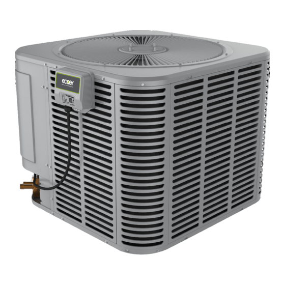
NOTE: Appearance of unit may vary.
22
23
IoT device does not ship with condensing unit.
24
29
Installation must be performed in accordance
36
with the requirements of NEC and CEC by
----------
38
authorized personnel only.
www.ecoer.com
03.2021
Advertisement
Table of Contents

Related Manuals for Ecoer EODA18H-2436


Summary of Contents for Ecoer EODA18H-2436
-
Page 1: Table Of Contents
ESI Outdoor Unit Installation Manual www.ecoer.com 1/38 Installation Manual Inverter Ducted Split Heat Pump (R-410A) 2-3-4-5 Ton Capacity Contents 1. Safety------------------------------------------------- 2. Unit Location Considerations------------------- 3. Position the Unit----------------------------------- 4. Refrigerant Line Considerations--------------- 5. Refrigerant Line Routing------------------------ 6. Refrigerant Line Brazing------------------------- 7. -
Page 2: Safety
ESI Outdoor Unit Installation Manual www.ecoer.com 2/38 1. Safety Read the following safety instructions before installing the unit or doing servicing work. WARNING may cause personal death or serious injury. CAUTION may lead to injury or structural damage under some conditions. - Page 3 ESI Outdoor Unit Installation Manual www.ecoer.com 3/38 CAUTION AUTHORIZED PERSONNEL ONLY This information is intended for use by individuals possessing adequate backgrounds of electrical and mechanical experience. Any attempt to repair central air conditioner or heat pump products may result in personal injury and/or property damage.
-
Page 4: Unit Location Considerations
Table 2-1 Condensing unit dimensions Unit Dimensions H x W x D (Inches) Model 24-15/16 x 29-1/8 x 29-1/8 EODA18H-2436 33-3/16 x 29-1/8 x 29-1/8 EODA18H-4860 Fig 2-2 External dimensions 2.3 Location Restrictions Exposure to a corrosive environment may shorten the life of the equipment, corrode metal parts, and/or negatively affect unit performance. - Page 5 ESI Outdoor Unit Installation Manual www.ecoer.com 5/38 Installation Clearance Requirement Avoid to install near bedrooms Ensure the top discharge area is unrestricted for at least 60 inches above the unit. Min. 60”unrestricted Do not locate condensing unit near bedrooms because normal operational sounds may be annoying.
-
Page 6: Position The Unit
ESI Outdoor Unit Installation Manual www.ecoer.com 6/38 3. Position the Unit When mounting the unit on a roof, be sure the roof will support the unit’s weight obtained from nameplate. Properly selected isolation is recommended to prevent sound or vibration transmission to the building structure. -
Page 7: Refrigerant Line Considerations
ESI Outdoor Unit Installation Manual www.ecoer.com 7/38 4. Refrigerant Line Considerations 4.1 Refrigerant Line Limits Use only the line sizes indicated in below table and determine required line length. If the suction line sets are greater than 50 feet, do not use a larger suction line than recommended. - Page 8 ESI Outdoor Unit Installation Manual www.ecoer.com 8/38 4.2 Refrigerant Line Insulation Liquid line Suction line The suction line must always be insulated. Insulation DO NOT allow the suction line and liquid line to come in direct (metal to metal) contact.
-
Page 9: Refrigerant Line Routing
ESI Outdoor Unit Installation Manual www.ecoer.com 9/38 5. Refrigerant Line Routing Comply with National, State, and Local Codes when isolating line sets from joists, rafters, walls, or other structural elements. Take precautions to prevent noise within the building structure due to vibration transmission from the refrigerant lines. -
Page 10: Refrigerant Line Brazing
ESI Outdoor Unit Installation Manual www.ecoer.com 10/38 6. Refrigerant Line Brazing Refer to below figures marked with digital number for line brazing procedures. Every figure is corresponding to the following illustrations. 1. Remove caps or plugs. Use a tool to deburr the line ends. Clean both internal and external surfaces of the tubing using an emery cloth. -
Page 11: System Leak Check
ESI Outdoor Unit Installation Manual www.ecoer.com 11/38 7. System Leak Check Leak check is required for the brazed line connections. 1. Pressurize the brazed refrigerant lines and indoor coil to at least 150 PSIG using dry nitrogen. 2. Check for leaks by using a soapy solution or bubbles at each brazed location. -
Page 12: Service Valves
ESI Outdoor Unit Installation Manual www.ecoer.com 12/38 9. Service Valves Leak check and evacuation must be completed before opening the service valves. The gas service valve must be opened BEFORE opening the Liquid Service Valve! 1. Remove service valve cap. -
Page 13: Electrical - Low Voltage
3: TA<-3°F (24V output) INDOOR UNIT OUTDOOR UNIT 4: OFF ONLY AVAILABLE TO ECOER THERMOSTAT WITH EAHATN-xx AIR HANDLER NOTES: 1. Be sure power supply agrees with equipment nameplate. 2. Power wiring and grounding of equipment must comply with local codes. - Page 14 ESI Outdoor Unit Installation Manual www.ecoer.com 14/38 Other Brand Thermostat Cool Only: Ecoer variable speed air conditioner (Dip ODU SW1-3 to ON) matches with fan coil. SW1-3 ON: AC SW1-3 OFF: HP Ecoer Air Conditioner Other Brand Fan Coil Thermostat Other Brand Thermostat 1H/1C: Ecoer variable speed heat pump matches with fan coil.
- Page 15 ESI Outdoor Unit Installation Manual www.ecoer.com 15/38 Other Brand Thermostat 2H/1C: Ecoer variable speed heat pump matches with fan coil. Optional Ecoer Condensing Unit (Heat Pump) Other Brand Fan Coil Thermostat * Jumper wire may be required for RH - RC. Refer to install guides of the thermostat you are using.
- Page 16 ESI Outdoor Unit Installation Manual www.ecoer.com 16/38 Other Brand Thermostat 1H/1C: Ecoer variable speed air conditioner (Dip ODU SW1-3 to ON) matches with furnace. Optional SW1-3 ON: AC SW1-3 OFF: HP Ecoer Air Conditioner Other Brand Furnace Thermostat * Jumper wire may be required for RH - RC. Refer to install guides of the thermostat you are using.
- Page 17 ESI Outdoor Unit Installation Manual www.ecoer.com 17/38 Other Brand Thermostat 2H/1C: Ecoer variable speed heat pump matches with furnace. Optional Must set n01 (HP Stop Temp.) and n03 (Duel-Fuel Temp.) to the same value. Ecoer Condensing Unit (Heat Pump) Other Brand...
- Page 18 Thermostat G Series Air Handler or Other Brand Fan Coil Ecoer Thermostat (EST01) Type 2 Cool Only with W2 output 1H/1C Ecoer variable speed air conditioner matches with gas or oil furnace. Optional SW1-3 ON: AC SW1-3 OFF: HP Ecoer Air Conditioner...
- Page 19 EST01 Wi-Fi Thermostat G Series Air Handler or Other Brand Fan Coil Ecoer Thermostat (EST01) Type 8 1H/1C with constant indoor fan speed Ecoer variable speed heat pump matches with fan coil. Optional Ecoer Condensing Unit (Heat Pump) EST01 Wi-Fi...
- Page 20 Thermostat E Series Air Handler Ecoer Thermostat (EST01) Type 10 2H/1C with constant indoor fan speed (Factory default) Ecoer variable speed heat pump matches with fan coil for 2 stage heating Optional Ecoer Condensing Unit (Heat Pump) EST01 Wi-Fi Thermostat G Series Air Handler or Other Brand Fan Coil Manufacturer reserves the right to change specifications or designs without notice.
- Page 21 ESI Outdoor Unit Installation Manual www.ecoer.com 21/38 Ecoer Thermostat (EST01) Type 11 2H/2C with two-stage fan control (G/G2) in cooling Ecoer variable speed heat pump matches with E series air handler and electric heat (Duel-fuel). Optional Ecoer Condensing Unit (Heat Pump) EST01 Wi-Fi...
-
Page 22: Electrical - High Voltage
Follow instructions on unit wiring diagram located on the inside of the control box cover. Fig 11-1 Read the Warning Label Power Supply Model Voltage Breaker EODA18H-2436 208/230V-1Ph-60Hz 24.4A EODA18H-4860 208/230V-1Ph-60Hz 32.5A 11.2 High voltage disconnect switch Install a separated disconnect switch at the condensing unit. -
Page 23: Start-Up
ESI Outdoor Unit Installation Manual www.ecoer.com 23/38 12. Start-up Prior to start-up the unit, connect IoT device if equipped with. Refer to IoT Installation and Units Warranty Registration Guide via ESS Pro App, At the same time, ensure chapters 5 to 11 have been completed. -
Page 24: System Charge Adjustment
ESI Outdoor Unit Installation Manual www.ecoer.com 24/38 13. System Charge Adjustment 13.1 Weigh-in method Weigh-in method can be used for the initial installation, or anytime a system charge needs to be replaced. Weigh-in method can also be used when power is not available on the job site or the ambient temperature is improper to use refrigerant coefficient and sub-cooling charge method. - Page 25 When the LED displays “--” for more than 20 minutes, stop charging and adjust the TXV opening to ensure required compressor suction superheat (Refer to the following page). Refrigerant coefficient The refrigerant coefficient is used to evaluate the refrigerant level in the ecoer system. Undercharged Overcharged Proper...
- Page 26 26/38 TIPS: How to adjust indoor TXV opening To keep the best Ecoer Smart Inverter (ESI) systems’ performance and reliability, be sure liquid line sub- cooling (SC) and compressor suction superheat (SH) meet our requirements. Target SC and SH 6~18゜F...
- Page 27 Repeat the steps above. Table 13-4 Designed sub-cooling degree Designed sub-cooling Model degree (SC) EODA18H-2436 10º F (±2º F) EODA18H-4860 8º F (±2º F) Fig 13-4 Measure the superheat or sub-cooling Manufacturer reserves the right to change specifications or designs without notice.
- Page 28 ESI Outdoor Unit Installation Manual www.ecoer.com 28/38 STEP3 ADJUST REFRIGERANT LEVEL TO ATTAIN PROPER GAUGE PRESSURE Add refrigerant if the sub-cooling is lower than the chart value. 1. Connect gauge hoses to refrigerant tank and liquid/gas service valves (Use gauge port instead of gas service valve for charge in heating).
-
Page 29: System Operation
ESI Outdoor Unit Installation Manual www.ecoer.com 29/38 14. System Operation 14.1 Default display LED on main control board can display the operating status of outdoor unit (ODU). SEG1 SEG2 SEG3 7 segment display instructions SEG1: Normally blank, but it displays codes “0 to 9” accordingly if there is damaged sensor and command response. - Page 30 ESI Outdoor Unit Installation Manual www.ecoer.com 30/38 Mode list (SEG3 Display) SEG1 SEG2 SEG3 Stop or standby SEG1 SEG2 SEG3 Ready to start-up SEG1 SEG2 SEG3 Cooling SEG1 SEG2 SEG3 Heating SEG1 SEG2 SEG3 Oil return SEG1 SEG2 SEG3 Defrost...
- Page 31 ESI Outdoor Unit Installation Manual www.ecoer.com 31/38 14.2 Field setting Outdoor condensing units’ functions can be applied by dipping switch and pressing buttons. 14.2.1 Setting by dip switches SW1 Dip switch Description NO . Setting item Status Content Reserved 2 or 4 Ton...
- Page 32 ESI Outdoor Unit Installation Manual www.ecoer.com 32/38 Default mode (Spot check) System states can be showed on the 7 segments display (LED) of outdoor unit. Press BS3 button to get code number and corresponding detailed information with an interval of one second.
- Page 33 ESI Outdoor Unit Installation Manual www.ecoer.com 33/38 Setting mode Press and hold BS1 button for 5 seconds to enter the parameter setting interface. The latest setting will be taken as the final one. Symbol Function Item Description 0 (factory) Normal (Energy Saving) mode...
- Page 34 ESI Outdoor Unit Installation Manual www.ecoer.com 34/38 14.3 Major components function Liquid Service Valve Heat Exchanger Gas Service Valve (RV) Gauge Port Fig 14-1 Refrigerant Circuit Name Symbol Function Adjusts refrigerant flow rate by changing the speed (RPS) based on Inverter compressor objective pressure.
- Page 35 ESI Outdoor Unit Installation Manual www.ecoer.com 35/38 14.4 Control logic description 14.4.1 Operation mode SW1_3=OFF (factory), ESI system uses Y/O/C signal to operate heat pump function. SW1_3=ON has been set, ESI system uses Y/C signal to run cooling only. Normal operation: ・Compressor control...
-
Page 36: Troubleshooting
ESI Outdoor Unit Installation Manual www.ecoer.com 36/38 15. Troubleshooting If the system does not operate properly besides any malfunctions. Check the system based on the following procedures. Symptoms Possible causes Solutions System does not • No 24 VAC for Y signal from •... - Page 37 37/38 Error codes List for Condensing Unit Error codes can be inquired by BS3 button, and seen on Ecoer Smart Service Pro App. Sign in App >Files >Service, refer to ESI (Ultra) service manual for troubleshooting details. Code Description...
-
Page 38: Wiring Diagram
ESI Outdoor Unit Installation Manual www.ecoer.com 38/38 16. Wiring Diagram EODA18H-2436 EODA18H-4860 Manufacturer reserves the right to change specifications or designs without notice. 03.2021... - Page 39 ESI Outdoor Unit Installation Manual www.ecoer.com 39/38 Manufacturer reserves the right to change specifications or designs without notice. 03.2021...
- Page 40 ESI Outdoor Unit Installation Manual www.ecoer.com 40/38 ©2021 ECOER INC. 3900 Jermantown Rd, Suite 150, Fairfax, VA 22030 Tel: 703-348-2538 www.ecoer.com Manufacturer reserves the right to change specifications or designs without notice. 03.2021...
Need help?
Do you have a question about the EODA18H-2436 and is the answer not in the manual?
Questions and answers