Ecoer 2436 Installation Instructions Manual
Split system heat pump
up to 20 seer
2-3-4-5ton capacity
r410a
Hide thumbs
Also See for 2436:
- Manual (15 pages) ,
- Installation instructions manual (32 pages) ,
- Installation manual (32 pages)
Table of Contents
Advertisement
ESI Outdoor Unit Installation Instruction
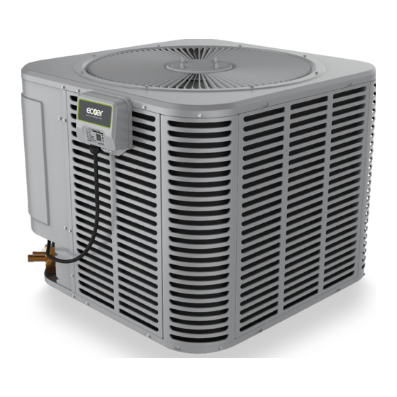
NOTE: Appearance of unit may vary.
The IoT gateway does not ship with outdoor unit.
Visit www.ecoer.com to obtain the documents for
IoT installation instructions.
Installation must be performed in accordance with
the requirements of NEC and CEC by authorized
personnel only.
All phases of this installation must comply with National, State and Local Codes.
IMPORTANT
This document is customer's property and is to remain with this unit. Please return it to customer
with service information upon completion of work.
These instructions do not cover all variations in systems or provide for every possible contingency
to be met in connection with the installation.
Should further information be desired or should particular problems arise which are not covered
sufficiently for the purchaser's purposes, the matter should be referred to your installing dealer or
local distributor.
Manufacturer reserves the right to change at any time for specifications or designs without notice and incurring obligations.
Installation Instructions
Split System Heat Pump
Up to 20 SEER
2-3-4-5Ton Capacity
R410A
Contents
1. Safety--------------------------------------------------
2. Unit Location Considerations--------------------
3. Position the Unit--------------------------------------
4. Refrigerant Pipe Considerations-----------------
5. Refrigerant Pipe Routing--------------------------
6. Refrigerant Pipe Brazing---------------------------
7. Refrigerant System Leak Check-----------------
8. Evacuation--------------------------------------------
9. Service Valves---------------------------------------
10. Electrical - Low Voltage----------------------------
11. Electrical - High Voltage---------------------------
12. Start Up------------------------------------------------
13. System Charge Adjustment----------------------
14. System Operation----------------------------------
15. Troubleshooting-----------------------------------------
1/61
2
4
6
7
9
10
11
11
12
13
14
15
16
20
29
05.2018
Advertisement
Table of Contents

Related Manuals for Ecoer 2436


Summary of Contents for Ecoer 2436
-
Page 1: Table Of Contents
NOTE: Appearance of unit may vary. 10. Electrical - Low Voltage---------------------------- The IoT gateway does not ship with outdoor unit. 11. Electrical - High Voltage--------------------------- Visit www.ecoer.com to obtain the documents for 12. Start Up------------------------------------------------ IoT installation instructions. 13. System Charge Adjustment---------------------- 14. -
Page 2: Safety
ESI Outdoor Unit Installation Instruction 2/61 1. Safety Read the following safety instructions before installing the unit or doing service work. WARNING may cause personal death or serious injury. CAUTION may lead to injury or structural damage under some conditions. WARNING HAZARDOUS VOLTAGE Failure to follow this warning could result in property damage, severe personal injury, or death. - Page 3 ESI Outdoor Unit Installation Instruction 3/61 CAUTION AUTHORIZED PERSONNEL ONLY This information is intended for use by individuals possessing adequate backgrounds of electrical and mechanical experience. Any attempt to repair a central air conditioning product may result in personal injury and/or property damage. INDOOR UNIT REQUIRED The indoor units must be matched with R-410A TXV.
-
Page 4: Unit Location Considerations
Table 2-1 Outdoor unit dimensions Unit Dimensions H x W x L(Inches) Model 24-15/16 x 29-1/8 x 29-1/8 2436 33-3/16 x 29-1/8 x 29-1/8 4860 Figure 2-2 Unit Dimensions Figure 2-2 External dimensions Manufacturer reserves the right to change at any time for specifications or designs without notice and incurring obligations. - Page 5 ESI Outdoor Unit Installation Instruction 5/61 2.3 Location Restrictions Installation Clearance Requirement Avoid to install near bedrooms Ensure the top discharge area is unrestricted for at least 60 inches above the unit. Do not locate outdoor unit near bedrooms since Min.
-
Page 6: Position The Unit
ESI Outdoor Unit Installation Instruction 6/61 3. Position the Unit When mounting the unit on a roof, be sure the roof will support the unit’s weight obtained from nameplate. Properly selected isolation is recommended to prevent sound or vibration transmission to the building structure. When installing the unit on a support pad, such as a concrete slab, consider the following: •... -
Page 7: Refrigerant Pipe Considerations
Model Suction pipe Liquid pipe Suction pipe connection Liquid pipe connection 2436 4860 4.2 Refrigerant Pipe Limits Use only the pipe sizes indicated in Table 4-1 and determine required pipe length. • Maximum pipe length = 100 feet. • Maximum elevation difference = 50 feet. - Page 8 ESI Outdoor Unit Installation Instruction 8/61 4.3 Refrigerant Pipe Insulation The suction pipe must always be insulated. DO NOT allow the liquid pipe and suction pipe to Suction pipe come in direct (metal to metal) contact. Liquid pipe Insulation Figure 4-3 Pipe insulation 4.4 Reuse Existing Refrigerant Pipes CAUTION If using existing refrigerant pipes, make sure that...
-
Page 9: Refrigerant Pipe Routing
ESI Outdoor Unit Installation Instruction 9/61 5. Refrigerant Pipe Routing Comply with National, State, and Local Codes when isolating pipe sets from joists, rafters, walls, or other structural elements. Take precautions to prevent noise within the building structure due to vibration transmission from the refrigerant pipes. -
Page 10: Refrigerant Pipe Brazing
ESI Outdoor Unit Installation Instruction 10/61 6. Refrigerant Pipe Brazing Refer to below figures marked with digital number for pipe brazing procedures. Every figure is corresponding to the following illustration. 1. Remove caps or plugs . Use a tool to deburr the pipe ends. Clean both internal and external surfaces of the tubing using an emery cloth. -
Page 11: Refrigerant System Leak Check
ESI Outdoor Unit Installation Instruction 11/61 7. Refrigerant System Leak Check Leak check is required for the brazed pipe connections. 1. Pressurize the brazed refrigerant pipes and indoor coil to at least 150 PSIG using dry nitrogen. 2. Check for leaks by using a soapy solution or bubbles at each brazed location. 150PSIG Figure 7-1 Charge dry nitrogen to the system Figure 7-2 Leak check... -
Page 12: Service Valves
ESI Outdoor Unit Installation Instruction 12/61 9. Service Valves Leak check and evacuation must be completed before opening the service valves. The Suction Service valve must be opened BEFORE opening the Liquid Service Valve! 1. Remove service valve cap. 2. Fully insert hex wrench into the stem and back out counterclockwise until valve stem just touches the rolled edge (approximately five turns.) 3. -
Page 13: Electrical - Low Voltage
Figure 10-1 Low voltage control wiring connection THERMOSTAT INDOOR UNIT OUTDOOR UNIT ONLY AVAILABLE TO ECOER THERMOSTAT WITH EAHATN SERIES INDOOR UNIT Notes: 1. Be sure power supply agrees with equipment nameplate. 2. Power wiring and grounding of equipment must comply with local codes. -
Page 14: Electrical - High Voltage
Figure 11-1 Read the Warning Label Power Supply Model Voltage Fuse Size 208/230V-1Ph-60Hz 24.4A 2436 208/230V-1Ph-60Hz 32.5A 4860 11.2 High voltage disconnect switch Install a separated disconnect switch at the outdoor unit. Field provided flexible electrical conduit must be used for high voltage wiring. -
Page 15: Start Up
ESI Outdoor Unit Installation Instruction 15/61 12. Start up Ensure chapters 5~11 have been completed. 1. Set the thermostat to OFF. 2. Turn on disconnect switch to apply power to the indoor and outdoor units. 4. Set the thermostat to ON. 3. -
Page 16: System Charge Adjustment
Charge amount for Charge multiplier for interconnecting Model charge Model indoor unit(oz) refrigerant tube length *2 <36K 2436 ≥36K The data on 0.6 oz/ft nameplate <60K 4860 ≥60K 1. Invalid for system with electric heaters or other third-party heaters whose capacity is 1.2 times of heat pump nominal heating capacity. - Page 17 ESI Outdoor Unit Installation Instruction 17/61 13.2 Auto charge mode Turn on the power supply, choose cooling mode on thermostat . Make sure the setting temperature is lower than room temperature for at least 5゜F. Press and hold BS4 button for five seconds, then SEG1 displays blinking “7”. After a minute, the system will go into AUTO charge mode to lock the compressor frequency.
- Page 18 Calculate sub-cooling value = ____________º F Add refrigerant if calculated sub-cooling value is lower than the designed one. Repeat the steps above. Table 13-4 Designed sub-cooling degree Model 2436 4860 Designed sub- 10º F(±2º F) 8º F(±2º F) cooling degree Figure 13-3 Measure the superheat or sub-cooling Manufacturer reserves the right to change at any time for specifications or designs without notice and incurring obligations.
- Page 19 ESI Outdoor Unit Installation Instruction 19/61 STEP3 Adjust refrigerant level to attain proper gage pressure. Add refrigerant if the sub-cooling is lower than the chart value. 1. Connect gages to refrigerant tank and unit as illustrated. 2. Purge all hoses. 3.
-
Page 20: System Operation
ESI Outdoor Unit Installation Instruction 20/61 14. System operation 14.1 Default display LED on main control board can display the operating state of outdoor unit (ODU). SEG1 SEG2 SEG3 7 segment display instructions SEG1: Normally blank, but it displays codes “1~9” accordingly if there is damaged sensor and demand control requirement. -
Page 21: Field Setting
ESI Outdoor Unit Installation Instruction 21/61 14.2 Field setting 14.2.1 Setting by dip switches Outdoor unit’s functions can be applied by pressing buttons and dialing switch on the job site. The following table shows the setting contents for “SW1” switch. Dip switch Description NO .... - Page 22 ESI Outdoor Unit Installation Instruction 22/61 ■ Mode change procedure Press BS1 button, the modes can be changed as follows. SEG1 SEG2 SEG3 Blinking BS1: Menu or back button Press buttons BS2: UP button BS3: Spot check and confirm button Press and hold Default mode BS1for 5 seconds.
- Page 23 ESI Outdoor Unit Installation Instruction 23/61 Default mode (Spot check) System state can be showed on the 7 segments display of outdoor unit. Press BS3 button to get code number and corresponding detailed information with an interval of one second. Example: Code number Detailed information...
- Page 24 ESI Outdoor Unit Installation Instruction 24/61 Setting mode Press and hold BS1 button for 5 seconds to enter the parameter setting interface. The latest setting will be taken as the final one. Symbol Function Item Description 0(factory) Normal mode Dehumidification *1 Mode choice High capacity mode *2 TA<-22F Forced heating stop...
- Page 25 ESI Outdoor Unit Installation Instruction 25/61 14.3 Major components function Liquid Stop Valve Heat Exchanger Gas Stop Valve Gauge Port Figure 14-1 Refrigerant Circuit Name Symbol Function Adjusts refrigerant flow rate by changing the frequency based on Inverter compressor objective pressure. Outputs heat exchanger capacity by adjusting rotation speed based on Inverter fan operating pressure.
-
Page 26: Operation Mode
ESI Outdoor Unit Installation Instruction 26/61 14.4 Control logic description 14.4.1 Operation Mode after 1 minute Operation in stop mode Thermostat OFF Thermostat ON Y=OFF (Y=ON) O be changed Pressure equalizing prior to Restart standby start up (compressor stops) Malfunction Longest 6 minutes /Thermostat OFF /O be changed... -
Page 27: Compressor Control
ESI Outdoor Unit Installation Instruction 27/61 14.4.2 Compressor control Standby PI control MAX 6 minutes for pressure Depending on the load of the room. equalization Start up control Directive control Differential control • Fixed speed in most cases • MAX time (cooling) ≤ 10 minutes MAX time (heating) ≤... -
Page 28: Fan Control
ESI Outdoor Unit Installation Instruction 28/61 14.4.3 Fan control Standby after Pressure control getting start signal Cooling fan control by high pressure • MAX STEP • Heating fan control by low pressure Start up control Directive control Cooling fan control by high pressure Fixed speed in most cases •... -
Page 29: Troubleshooting
ESI Outdoor Unit Installation Instruction 29/61 15. Troubleshooting If the system does not properly operate besides the malfunctions. Check the system based on the following procedures. Symptoms Possible causes Solution System does not start up but the • No 24 VAC signal from indoor unit Provide 24 VAC signal and make sure digital tube shows or thermostat... - Page 30 ESI Outdoor Unit Installation Instruction 30/61 15.1 Error code List for Outdoor Unit Past error codes can be spot checked from default mode by BS1~BS3 buttons, and seen from Ecoer Smart Service App. Error Code Description Legend High pressure protection System locks up when P1 has occurred six times in 3 hours.
- Page 31 ESI Outdoor Unit Installation Instruction 31/61 No Display The unit energized but the digital tube shows nothing 1.Error definition: No display on main control board even though the unit has been powered ON. 2.Possible causes: Damaged noise filter. Damaged inductance. ...
- Page 32 ESI Outdoor Unit Installation Instruction 32/61 Display High pressure protection 1.Error definition: P1: The detected high pressure is no less than 566psig. E1: System locks up when P1 has occurred six times within 3 hours. 2.Possible causes: Service valves are closed. ...
- Page 33 ESI Outdoor Unit Installation Instruction 33/61 Display Low pressure protection in cooling mode 1.Error definition: P2: The detected low pressure in cooling mode is less than 24.5psig. E2: System locks up when P2 has occurred six times within 3 hours. 2.Possible causes: ...
- Page 34 ESI Outdoor Unit Installation Instruction 34/61 Display Discharge temperature protection 1.Error definition: P3: The maximum detected discharge temperature(TD) is no less than 248F. E3: System locks up when P3 has occurred six times within 3 hours. 2.Possible causes: Too little refrigerant remains in the system. ...
- Page 35 ESI Outdoor Unit Installation Instruction 35/61 Display Discharge temperature sensor is disconnected or damaged 1.Error definition: When TD<TC-9F for 20 minutes, or the suction superheat(SH) is no less than 9F with TD<TL-9F lasts 20 minutes. TC: The saturation temperature of high pressure 2.Possible causes: ...
- Page 36 ESI Outdoor Unit Installation Instruction 36/61 Display Module temperature protection 1.Error definition: P5: The detected value of module temperature (TF) is no less than specific value. 2~3Ton: 181F 4~5Ton: 176F in cooling mode 167F in heating mode E5: System locks up when P5 has occurred six times within 3 hours. 2.Possible causes: ...
- Page 37 ESI Outdoor Unit Installation Instruction 37/61 Display Over-current protection for compressor 1.Error definition: P6: The detected compressor current is over the maximum allowable value. 2~3Ton: 16A 4~5Ton: 20A E6: System locks up when P6 has occurred six times within 3 hours. 2.Possible causes: ...
-
Page 38: Cooling Mode
ESI Outdoor Unit Installation Instruction 38/61 Display Liquid slugging protection 1.Error definition: This control is to prevent compressor from damaging because of liquid slugging. When SH is less than 9.0F as well as discharge superheat (DSH=TD-TC) is less than 14.4F for 30 minutes, starting to accumulate the liquid slugging time. Report the error code P7 once if it lasts for 60 minutes. -
Page 39: Heating Mode
ESI Outdoor Unit Installation Instruction 39/61 Heating mode Connect a pressure gauge to liquid stop valve, compare the gauged pressure with the transduced one by high pressure sensor. Check whether the discharge temperature sensor is properly Reset the sensor or reconnect the seated on the discharge pipe and securely connected to CN7 wire terminal on the main control board. - Page 40 ESI Outdoor Unit Installation Instruction 40/61 Display Low compressor voltage protection 1.Error definition: P8: The detected compressor voltage by main chip is less than 310VDC. E8: System locks up when P8 has occurred three times in 60 minutes. 2.Possible causes: ...
- Page 41 ESI Outdoor Unit Installation Instruction 41/61 Display Ambient temperature sensor fault (TA) 1.Error definition: The outside temperature sensor (TA) is short circuit or open circuit. 2.Possible causes: Damaged main control board Loose connection at port on main control board. ...
- Page 42 ESI Outdoor Unit Installation Instruction 42/61 Display Suction temperature sensor fault (TS) 1.Error definition: The suction temperature sensor (TS) is short circuit or open circuit. 2.Possible causes: Damaged main control board Loose connection at port on main control board. ...
- Page 43 ESI Outdoor Unit Installation Instruction 43/61 Display Liquid temperature sensor fault (TL) 1.Error definition: The liquid temperature sensor (TL) is short circuit or open circuit. 2.Possible causes: Damaged main control board Loose connection at port on main control board. ...
- Page 44 ESI Outdoor Unit Installation Instruction 44/61 Display Condenser coil temperature sensor fault (TH) 1.Error definition: The condenser coil temperature sensor (TH) is short circuit or open circuit. 2.Possible causes: Damaged main control board Loose connection at port on main control board. ...
- Page 45 ESI Outdoor Unit Installation Instruction 45/61 Display Discharge temperature sensor fault (TD) 1.Error definition: The discharge temperature sensor(TD) is short circuit or open circuit. 2.Possible causes: Damaged main control board Loose connection at port on main control board. ...
- Page 46 ESI Outdoor Unit Installation Instruction 46/61 Display Module temperature sensor fault (TF) 1.Error definition: The module temperature sensor (TF) is short circuit or open circuit. 2.Possible causes: Damaged main control board Loose connection at port on main control board. ...
- Page 47 ESI Outdoor Unit Installation Instruction 47/61 Display High pressure sensor fault (HP) 1.Error definition and method to check: The high pressure sensor is open or shorted. The voltage between CN10 pin(1) and (2) is not in the range 0.59~4.76VDC. CN10 IC A/D White input...
- Page 48 ESI Outdoor Unit Installation Instruction 48/61 Display Low pressure sensor fault (LP) 1.Error definition and method to check: The low pressure sensor is open or shorted. The voltage between CN9 pin(1) and (2) is not in the range 0.70~4.50VDC. IC A/D White input black...
- Page 49 ESI Outdoor Unit Installation Instruction 49/61 Display Communication fault between main chip and INV drive chip 1.Error definition and method to check: Communication fault between the main control chip and inverter chip. 2.Possible causes: Loose connection at CN21 terminal. ...
- Page 50 ESI Outdoor Unit Installation Instruction 50/61 Display Ambient temperature limit operation 1.Error definition and method to check: H1: The detected ambient temperature is absolutely prohibited for cooling. TA<14F or ≥140F H2: The detected ambient temperature is absolutely prohibited for heating. TA ≥...
- Page 51 ESI Outdoor Unit Installation Instruction 51/61 Display Abnormal switch alarm for 4-way valve 1.Error definition: 4-way valve switch incompletely after defrost operation or from cooling mode. If TH ≥ TL+5.4F and TH ≥ TA+5.4F, report this alarm. 2.Possible causes: Damaged 4-way valve ...
- Page 52 ESI Outdoor Unit Installation Instruction 52/61 Display Condenser coil temperature sensor is disconnected or damaged 1.Error definition: The coil temperature sensor (TH) is short circuit or open circuit. 2.Possible causes: Damaged main control board The condenser coil temperature is wrongly seated ...
- Page 53 ESI Outdoor Unit Installation Instruction 53/61 Display EEPROM fault 1.Error definition: Data cannot be correctly received from the EEPROM, a type of memory component, remembers contents even though the power supply is turned off. 2.Possible causes: Damaged main control board External interference (e.g.
- Page 54 ESI Outdoor Unit Installation Instruction 54/61 Display Compressor INV module ~ protection 1.Error definition: C0: Critical OV Fault-COVP C1: DC bus over-voltage protection-OVP C2: DC bus under-voltage protection-LVP C3: Over current protection-OCP C4: ZeroSqdFlt C5: Synchronization - PwmsyncErr C6: Phase loss protection for 3-phase lines U, V, W in compressor-PhslossFlt C7: Compressor speed inconsistent fault C8: Compressor speed instability C9: Compressor speed difference between given transient variation and actual operation...
- Page 55 ESI Outdoor Unit Installation Instruction 55/61 15.2 Sensor Charactics Resistance of Temperature sensor A* (TS,TH,TA,TL) Temp. Temp. Resistance Voltage Temp. Temp. Resistance Voltage Temp. Temp. Resistance Voltage (°C) (°F) (KΩ) (°C) (°F) (KΩ) (°C) (°F) (KΩ) 104.86 0.53 71.6 11.49 2.10 147.2 2.02...
- Page 56 ESI Outdoor Unit Installation Instruction 56/61 Resistance of Temperature sensor B* (TF,TD) Temp. Resistance Voltage Temp. Resistance Voltage Temp. Resistance Voltage Temp.(°C) Temp.(°C) Temp.(°C) (°F) (KΩ) (°F) (KΩ) (°F) (KΩ) 177.8 6.67 2.89 517.84 0.27 87.8 43.10 1.72 179.6 6.46 2.90 -2.2 489.93...
- Page 57 ESI Outdoor Unit Installation Instruction 57/61 Low Pressure Sensor Voltage Characteristics C* Low pressure Low pressure Resistance Output Low pressure Low pressure Resistance Output (MPa) (psig) (KΩ) voltage(V) (MPa) (psig) (KΩ) voltage(V) 0.10 14.5 49.51 0.70 0.68 98.6 13.61 1.86 0.11 47.91 0.72...
- Page 58 ESI Outdoor Unit Installation Instruction 58/61 High Pressure Sensor Voltage Characteristics D* High pressure High pressure Resistance Output High pressure High pressure Resistance Output (MPa) (psig) (KΩ) voltage(V) (MPa) (psig) (KΩ) voltage(V) 14.5 60.60 0.59 449.5 4.55 3.20 51.74 0.67 4.22 3.28 43.5...
-
Page 59: Wiring Diagram
ESI Outdoor Unit Installation Instruction 59/61 15.3 Wiring Diagram EODA18H-2436 Manufacturer reserves the right to change at any time for specifications or designs without notice and incurring obligations. 05.2018... - Page 60 ESI Outdoor Unit Installation Instruction 60/61 EODA18H-4860 Manufacturer reserves the right to change at any time for specifications or designs without notice and incurring obligations. 05.2018...
- Page 61 ESI Outdoor Unit Installation Instruction 61/61 Notes: Manufacturer reserves the right to change at any time for specifications or designs without notice and incurring obligations. 05.2018...
- Page 62 ESI Outdoor Unit Installation Instruction 62/61 Manufacturer reserves the right to change at any time for specifications or designs without notice and incurring obligations. 05.2018...
Need help?
Do you have a question about the 2436 and is the answer not in the manual?
Questions and answers