Table of Contents
Advertisement
Quick Links
Ergänzende Anleitung
zum Betrieb über die
RS-Schnittstelle
Bitte sorgfältig beachten!
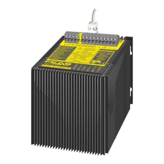
Für die Modelle:
- LDR8024-RS -
Stand / as at: 01.11.2022
Postfach 1521
D - 22905 Ahrensburg
© 2022
Supplementary instructions
for operation
via the RS interface
Please observe carefully!
Complementing the:
- konform
Telefon: +49 4102 42082
E-Mail: verkauf@feas.de
Fax: +49 4102 40930
Internet: www.feas.de
1. RS-232 / RS-485 Schnittstelle allgemein
Über die RS-232/RS-485-Schnittstelle kann das LDR
Statusmeldungen an ein Terminalprogramm ausgeben (siehe
Abschnitt 3) und Kommandos entgegennehmen.
Dazu muss das LDR über ein RS-232- oder RS-485-Kabel
mit einem PC verbunden sein (siehe Abschnitt 2). (Zuvor sind
die zwei schwarzen Schrauben neben der RS-Buchse mit
einem Inbusschlüssel, 2,5mm, zu entfernen.)
Ein Anschlusskabel kann separat als Zubehör bestellt
werden (FEAS Art.-Nr.: 99046).
2. RS-232/RS-485-Anschluss
Das Gerät kann über die D-Sub-9 Buchse des LDR80-RS an
einen Computer angeschlossen werden. Dabei können RS-232-
oder RS-485-Daten ausgetauscht werden. Entscheidend ist
dabei die Steckerbelegung des verwendeten Schnittstellen-
kabels gemäß untenstehender Tabellen.
2.1 RS-232 - Betrieb
Vor Inbetriebnahme des LDR über die RS-232-Schnittstelle
müssen die Pins 3-5 und 4-5 verbunden werden.
2.2 RS-485 - Betrieb / Abschlusswiderstand
Vor Inbetriebnahme des LDR über die RS-485-Schnittstelle
müssen die Pins 3-5 verbunden werden.
Außerdem muss ein Abschlusswiderstand zwischen den
Pins 7-8 angebracht werden. Erfahrungsgemäß reicht ein 120
Widerstand. Mit zusätzlicher Kabellänge kann sich der
Widerstandswert erhöhen (siehe entsprechende Richtlinien im
Internet).
2.3 RS-232/RS-485 Buchsenbelegung / Pins
D-Sub 9-polig Buchse (female)/
D-Sub 9-pin socket (female)
5 4 3 2 1
9
8
7
6
Ansicht von außen/outer view
2.4 RS-232/RS-485 Steckerbelegung
RS-232
Pin
connection
description
1
TxD RS232
Output
2
RxD RS232
Intput
3
4
5
GND
GND
6
n.c.
7
n.c.
8
n.c.
9
n.c.
ground potential
D-Sub 9 housing
1. RS-232 / RS-485 Interface general
Via the RS-232 / RS-485 interface the LDR can send
status messages to a terminal programme (see section 3)
and accept commands.
For this purpose, the LDR must be connected to a PC via a
special RS-232 or RS-485 cable (see section 2). (Before that,
remove the two black screws next to the RS socket with an
Allen key, 2.5mm).
A connection cable can be ordered separately as an
accessory (FEAS art. no.: 99046).
2. RS-232/RS-485 - Connection
The unit can be connected to a computer via the D-Sub-9 socket
of the LDR80-RS. RS-232 or RS-485 data can be exchanged. The
decisive factor here is the pin assignment of the interface cable
used (see tables below).
2.1 RS-232 Operation
For running the LDR with via the RS-232-interface connect PINs 3-
5-4 before first operation.
2.1 RS-485 Operation
For running the LDR with via the RS-485-interface connect PIN 3
and PIN 4 before first operation.
A terminating resistor has to be inserted between pins 7-8.
Ω
Ω
Typically a 120
resistor is sufficient. With additional cable length,
the resistance value may increase (see corresponding guidelines
on the Internet).
2.3 RS-232/RS-485 jack assignment / pins
Eingangswechselspannung
Herstellung gem.
AC - Input voltage range
Manufactured acc.
Eingangsgleichspannung
DC - Input voltage range
VDE
0100, 0110, 0113
Akkukapazität
Accu-capacity
EN
61558-2-16
EN
50178
Ausgangsgleichspannung
DC - Ouput voltage
IEC
1000-4-2,4,5
EN
61000-6-1,2,3,4
Ausgangsstrom
Output current
EN
60950,
EN
EN
61000-4-2,3,4,5,6
Ausgangsschutz
Output - protection
EN
61000-4-8,11
EN
61000-3-2
Ausgangsleistung
Output power
UL
1950,
UL
CSA
-C22.2
Verbrauch
Consumption
Arbeitstemperaturbereich
Temperature - range
Prüfspannung E/A
Test voltage I/O
Made in Germany
2.4 RS-232/RS-485 connector pin assignment
RS-485
Pin
connection
description
1
n.c.
2
n.c.
3
4
n.c.
5
GND
6
GND_RS485
7
B
RS-485 DATA
8
A
RS-485 DATA
9
U+
ground potential
D-Sub 9 housing
62368
508
GND_485
voltage
Advertisement
Table of Contents

Subscribe to Our Youtube Channel
Summary of Contents for FEAS LDR8024-RS
- Page 1 Für die Modelle: Complementing the: - LDR8024-RS - werden (FEAS Art.-Nr.: 99046). accessory (FEAS art. no.: 99046). 2. RS-232/RS-485-Anschluss 2. RS-232/RS-485 - Connection Das Gerät kann über die D-Sub-9 Buchse des LDR80-RS an The unit can be connected to a computer via the D-Sub-9 socket of the LDR80-RS.
- Page 2 PuTTY). (screenshots see next pages) (Screenshots siehe nächste Seiten) (Ein Terminalprogramm finden Sie auch unter feas.de zum (A terminal program can also be found at feas.com for free Current Current - NORMAL kostenlosen Download, im Downloadbereich des LDR80-RS)
- Page 3 The screen displays for RS-232 and RS-485 differ only in the unterscheiden sich nur in der Kopfzeile: header: RS-232: “FEAS BATTERY CONTROL – RS232“ RS-232: "FEAS BATTERY CONTROL - RS232" RS-485: „FEAS BATTERY CONTROL – RS485“ RS-485: "FEAS BATTERY CONTROL - RS485"...
- Page 4 Kein Netz, Last am Ausgang getrennt, No line voltage, DC is switched off, 7. RS-232/RS-485-Pufferzeiteinstellung im Detail 7. RS-232/RS-485 screen displays in detail trotzdem geringfügige Batterieentladung nevertheless slight battery discharge Pufferzeiteinstellung - Ladebetrieb, getrennte Last Setting of remain time - Charge Operation, DC OFF The buffer time setting is only possible in mains Die Pufferzeiteinstellung ist nur im Netzbetrieb operation and when the load is disconnected.
- Page 5 Pufferzeiteinstellung - Wert für die Reduzierung Setting Remaining Time - Value for the decrease 8. RS-232/RS-485 - Abschaltfunktionen 8. RS-232/RS-485 - Shutdown functions 8.1 DC output off 8.1 Abschaltung Ausgang (Lasttrennung) The DC output can also be switched off (command: “O“) or on Die Ausgangsspannung kann auch über die RS-Schnittstelle abgeschaltet (Befehl: “O“) oder freigegeben (Befehl: “S“) werden (command: “S“) via the RS interface (see section 5).
- Page 6 LED „Datenaustausch“ und die LED „Temperatur / Inhibit" lights up additionally until finally all LEDs go Postfach 1521 Telefon: +49 4102 42082 E-Mail: verkauf@feas.de Inhibit“ leuchtet zusätzlich, bis letzendlich alle LEDs out when the device is switched off. beim Abschalten des Geräts ausgehen.


Need help?
Do you have a question about the LDR8024-RS and is the answer not in the manual?
Questions and answers