
Subscribe to Our Youtube Channel
Related Manuals for Loring Merlin A15


Summary of Contents for Loring Merlin A15
- Page 1 Merlin 15K Batch Roasters 3200 Dutton Ave. #413, Santa Rosa, CA 95407 Phone (707) 526‐7215 www.smartroaster.com ...
-
Page 2: Table Of Contents
OPERATION MANUAL MERLIN A-15 KILO ROASTER By LORING SMART ROAST 3200 Dutton Ave. #413, Santa Rosa, CA 95407 Phone 707 526-7215, Fax 707 526-3815 TABLE OF CONTENTS DAILY OPERATING INSTRUCTIONS FOR MERLIN A-15 IMPORTANT SAFETY INSTRUCTIONS • Read all instructions before proceeding START UP: FIRST THINGS FIRST •... - Page 3 SETUP SCREEN OPTIONS • Configure many roaster variables RECOMMENDED MAINTENANCE MAINTENANCE: DAILY • Some basic chores MAINTENANCE: WEEKLY • Cleaning the cooler tray • Vacuum particulate mater from the cooler ducting under the roaster • Clean vacuum elevator filter • Bearing squeak MAINTENANCE: MONTHLY •...
-
Page 4: Important Safety Instructions
MERLIN A15 15KG BATCH ROASTER IMPORTANT SAFETY INSTRUCTIONS The roaster MUST be placed on a flat level surface capable of supporting its weight. Keep area around roaster clean and dry and clear of obstructions as required by local safety regulations. - Page 5 Circulation Fan Adjustment Slide Thermal Coupler Temperatures Burner Percentage are indicated on the Graph by their given color. Burner Adjustment Up and Down Buttons Burner Adjustment Slide General Information Time and Temperature Graph. Picture ON and OFF LOAD GREEN button indicates to button for the the computer that the Green has been Cooler Paddle...
-
Page 6: Start Up: First Things First
START-UP Empty the chaff collector drum. Reinstall the chaff drum and be sure that the locking clamps are securely latched. Be sure all cooler ducting is installed with gaskets and clamps are latched tight. Check to see that the cooling hopper is empty and close the cooler discharge gate. Close the roaster door. -
Page 7: Manual Mode: Starting A Roast
Background turns green and the Button turns green and says “CIRC FAN” turns on when “ON” when burner is lit. “Burner On” is requested. Mode Indicator IDLE Mode ROASTING POST ROAST COOL DOWN Picture 002 Picture 003 Picture 004 Picture 005 Touch Yellow “Batch”... - Page 8 Select the name of the product you are about to roast from the list of product names you entered under the “SELECT PRODUCT” button of the “ROAST LOG COMMENTS” tab. It will now appear on the main “MANUAL ROAST” screen (see Picture 006, 007, 008) At this time, you may also select a “BASELINE”...
- Page 9 Touch to Adjust Click here to go back ENDPOINT to the Main Screen Roast Log Comments (Picture 007) Picture 007 Picture 006 Select Products brings up You can scroll through your product list by your Product List touching “<<Last Product” or “Next Product>>” (Picture 008) White line is a profile from history.
-
Page 10: Manual Mode: During The Roast
MANUAL MODE: DURING THE ROAST During the roast, you may jump between the “TREND DISPLAY”, “ROAST LOG COMMENTS”, and the “PLOT” tabs . You may also enter (see Picture 012, 013, 014 and 015) “SETUP” and make changes to some of the basic values and parameters of the roaster. On the “ROAST LOG COMMENTS”... -
Page 11: Manual Mode: Ending The Roast
Trend Toggle back and forth Plot View View Picture 015 Picture 014 MANUAL MODE: ENDING THE ROAST At the end of the roast the screen will flash “END OF ROAST” and the horn will sound till the door is opened. The horn may be silenced with the “SILENCE HORN” button on the screen. - Page 12 RECIPE”, “BASELINE”, and “ROAST PROFILE MODES” . Click the (see Picture 017) “BURNER / RECIPE” button and it will turn green. Press the “CAPTURE LAST MANUAL RUN FOR BASELINE PLOT” to capture the baseline, then “CAPTURE LAST MANUAL RUN FOR BURNER RECIPE” button to capture the recipe. You must now name the recipe and save it under the new name.
-
Page 13: Manual Mode: Cool Down
Touch here to name your recipe. Then First touch BURNER touch “Save Recipe” button. RECIPE and it will turn Picture 020 Picture 021 green. Second touch “Capture Last Manual Run for Base Line Plot” Third touch “Capture Last Manual Run for Burner Recipe” Fourth touch “Edit Burner Recipe”... -
Page 14: Recipe Mode: Some Facts About Recipes
To create or change a recipe (or profile) you must first Login. By default, the password is 3333. This may be changed at startup or later via the Internet or, by a field service engineer from LORING SMART ROAST. A recipe can only be “captured” from a batch that you roast in “MANUAL MODE”, but can be created in other ways like creating from scratch using the “EDIT BURNER RECIPE”... - Page 15 baseline associated with it until the program is run and the baseline thus generated is saved with the recipe using the same name. You must have just run (or you must load) the recipe to which you want to add the baseline before changing the name or saving the recipe.
-
Page 16: Recipe Mode: Starting A Roast
Once saved the new name of the recipe will appear here. Picture 031 RECIPE MODE: STARTING A ROAST Click the purple “ROAST / PROFILE” button above the trend screen on the main screen . A new screen will appear allowing you to choose between Burner Recipe, (see Picture 032) Baseline, and Roast Profile modes. - Page 17 automatically. The roast timer will start at this time and the drum drive will start automatically if it is not already on. Once the green bean drop valve closes, the burner will go to the first burner set point of the recipe.
-
Page 18: Recipe Mode: During The Roast
Touch here to change “END POINT” temperature. Touch here to “GO TO MANUAL” mode. Now in “BURNER RECIPE RUN MODE” Picture 038 RECIPE MODE: DURING THE ROAST The recipe software is now in control of the roast. Manual burner adjustments can be made and will remain in affect till the recipe reaches the next control point. - Page 19 Touch “TREND DISPLAY” Picture 039 Picture 040 Touch “RECIPE SETTINGS” Picture 041 Picture 042 Enter your comments on these 3 lines. Touch “ROAST LOG COMMMENTS” You may enter SETUP hanges to some of the basic values and parameters. See Picture 47. Picture 043 Picture 044 Rev 10-15-12...
-
Page 20: Recipe Mode: Ending The Roast
Touch “PLOT DISPLAY” Picture 046 Picture 045 Picture 047 Picture 048 RECIPE MODE: ENDING THE ROAST The endpoint temperature is part of the recipe . The Amber light on the front (see Picture 049) of the consolet will flash @ 20 degrees F (9 deg C) before it has reached the endpoint temperature . -
Page 21: Recipe Mode: Post Roast & Idle Mode
Endpoint Temperature Amber Flasher Picture 050 Picture 049 Silence Horn Picture 052 Picture 051 Touch here to disable the “End Of Roast” Buzzer. Picture 054 Picture 053 RECIPE MODE: POST ROAST & IDLE MODE Rev 10-15-12... - Page 22 “POST-ROAST” exists because there is residual smoke in the roaster after the coffee is out of the roaster drum. The burner remains on for 3-minutes after the end of the roast to eliminate it and this time is called “POST-ROAST” .
-
Page 23: Recipe Mode: Cool Down
Batch Number will also show on the Email detail. Agtron & Weights Picture 058 Picture 057 RECIPE MODE: COOL DOWN At the end of the day, or even on long breaks from roasting, when the roaster is in “IDLE” or “POST ROAST” you can switch the roaster to “COOL DOWN”. In cool down, the burner is shut off along with all other motors except the circulating fan. - Page 24 To Cool Down from “BURNER Now you can touch RECIPE RUN MODE”, you must “GO TO COOL “GO TO MANUAL” mode DOWN” Picture 61 Picture 62 Rev 10-15-12...
-
Page 25: Roast Profile Mode: Some Facts About Profiles
To create or change a profile (or recipe) you must first Login. By default, the password is 3333. A field service engineer from LORING SMART ROAST may change this at startup or later via the Internet. Login on the Setup Page from the Roast Log Comments tab. -
Page 26: Roast Profile Mode: Starting A Roast
Minute #2. Each slider represents 6 seconds. Touch here to take RETURN AIR temperature reading you to minute #7 Picture 064 Picture 063 Toggle button to switch from “DROP ON BEAN TEMP” OR Touch here to capture your base line “DROP ON RETURN AIR TEMP”... - Page 27 Click the purple “RECIPE / PROFILE” button above the trend screen on the main screen . A new screen will appear allowing you to choose between Burner Recipe, (see Picture 068) Baseline, and Roast Profile modes . Click the “ROAST PROFILE” button at the (see Picture 069) top of the right hand column and it will turn green.
- Page 28 Touch “ROAST PROFILE” to turn it green. Then Touch “LOAD FILE FROM MEMORY Then select your product Touch “RECIPE/PROFILE” Picture 068 Picture 069 Select Product Then touch “Recipe/Profile Run” Picture 070 Picture 071 Change “ENDPOINT” temperature if needed. Now in You can change the “ENDPOINT”...
-
Page 29: Roast Profile Mode: During The Roast
PRESS TO START PROFILE RUN Roaster Above Drop Temp-Open Door Picture 074 Picture 075 Picture ROAST PROFILE MODE: DURING THE ROAST The profile software is now in control of the roast. During the roast, you may jump between the “TREND DISPLAY”, “PROFILE SETTINGS”, “ROAST LOG COMMENTS”... - Page 30 192.168.1.200 but you can check on the information tab of the “SETUP” screen if that doesn't work. You may also try another browser. They don't all support this but IE and Firefox usually work. A Tight VNC password dialog box will open and you then enter one of your two passwords.
-
Page 31: Roast Profile Mode: Ending The Roast
“TimeSinceCrack” is only a timer and must be manually activated. Picture 081 ROAST PROFILE MODE: ENDING THE ROAST The endpoint temperature is set manually and is not part of the profile. 20 degrees F (9 deg C) before it is reached the amber flasher on the front of the consolet will start flashing. As the endpoint approaches the flasher will flash faster . -
Page 32: Roast Profile Mode: Post Roast & Idle Mode
Touch each line and enter your notes, or use your VPN connection and use your PC to enter your notes. Touch “ROAST LOG COMMENTS” then this screen will appear. Picture 084 ROAST PROFILE MODE: POST ROAST & IDLE MODE “POST-ROAST” exists because there is residual smoke in the roaster after the coffee is out of the roaster drum. - Page 33 Touch “Idle HI Limit Temp” to adjust the point the burner turns back on during Idle Mode. Adjustable time duration for the Cooler Tray Fan. Touch “Idle Low Limit Temp” to adjust the point the burner turns off during Idle Mode. Picture 085 Picture 086 Rev 10-15-12...
-
Page 34: Roast Profile Mode: Cool Down
ROAST PROFILE MODE: COOL DOWN At the end of the day, or even on long breaks from roasting, when the roaster is in “IDLE” or “POST ROAST” you can switch the roaster to “COOL DOWN”. In cool down, the burner is shut off and the circulating fan speeds up. Air is circulated and after a short time the purge gate is opened so all the air is replaced with cool room air constantly. -
Page 35: "Setup Screen" Options
“SETUP SCREEN” OPTIONS Your needs can be better suited by Customizing the Roaster. A log in procedure helps to insure that only authorized employees make changes to key things like roast profiles and burner recipes. The default log in password is 3333 and can be changed at the customer's request. - Page 36 Chaff Quench timer allows you to fine tune the amount of quench that is sprayed on the chaff inside the chaff drum at the end of each roast, automatically. The Quencher is adjustable in 1/10 of a second increments. Default is 2.5 seconds. Chaff will be unburned and have a crusty layer followed by a fluffy layer.
- Page 37 the roast further than you had planned when you set the endpoint. Therefore, a button will appear on the screen at the end of the roast that allows you to turn off the buzzer, but it will be back the next roast unless you decide to disable it here on the setup screen. Burner Configuration is accessible only by LSR field service technicians.
-
Page 38: Recommended Maintenance
RECOMMENDED MAINTENANCE MAINTENANCE: DAILY It is important to get to know your roaster so you know how long, how many batches you may roast, before the chaff barrel needs to be emptied. It should be done at least once a day, but may be required more often if your production level is high. - Page 39 Install the 2 knobs Use small screw driver Picture 003 Picture 004 Screen Installation Picture 006 Picture 005 VACUUM PARTICULATE MATER FROM COOLER DUCTING UNDER ROASTER Lift off the right side panel of the roaster under the drum and place it in a safe (Picture 007) place where it will not be knocked over and scratched.
- Page 40 Remove Panel Note: Longer straight piece goes here Picture 007 Picture 008 Remove clamp Clean burner hole of cyclone Picture 010 Picture 009 CLEAN THE CHAFF BARREL Remove the chaff barrel and after emptying the chaff, clean the underside of the barrel lid.
-
Page 41: Clean Vacuum Elevator Filter
Scrape clean Picture 011 Picture 012 CLEAN VACUUM ELEVATOR FILTER If the vacuum elevator seems slow or turns off before all the beans are lifted and you have to start it again, chances are that the filter needs cleaning. The vacuum elevator filter is made of potted silicone over stainless steel paper so it can take the heat should it ever be required to. -
Page 42: Maintenance: Monthly
MAINTENANCE: MONTHLY CHECK QUENCH SPRAY NOZZLES Check that the quench spray nozzles are flowing freely. They can become plugged with coffee goop over time, especially the roast quench, because of the way many people choose to roast, it is often disabled for much of the time. The roast quench spray nozzle is located on the cyclone side of the flange that mounts the cyclone to the air circulating fan (Picture 015, 016) It is removed with four thumb knobs. -
Page 43: Maintenance: Annually Or As Needed Based On Your Production
INSPECT AND CLEAN COOLER VENTING SYSTEM To clean the cooler fan, cool the roaster down then turn off the power at the control panel. Next, switch the power off at the fused disconnect on the front of the main electrical enclosure by rotating the handle 90 degrees to the left. - Page 45 APPROVALS / CERTIFICATIONS COMPONENT MANUFACTURE PART # UL CE CSA FM RU OTHER CONTROL ELECTRONICS: Process Logic Controller KOYO 250-1 Touchscreen BEIJER T100 Variable Frequency Drive YASKAWA J1000 DC Power Supply IDEC PS5R-SF24 Serial to Ethernet Converter MOXA Nport 5110 Ethernet Hub MOXA EDS-205A...
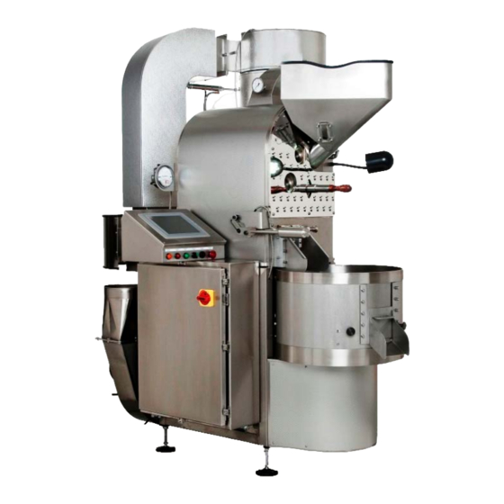
- Page 46 COMPONENT IDENTIFICATION FRONT OF ROASTER A-15 Vacuum Elevator Motor Green bean hopper site glass Hopper release clamp Combustion air pressure gauge & burner firing rate indicator Chamber quench valve Coffee Tryer/Sampler Cyclone Manual door sensor Chaff Barrel quench 3200 Dutton Ave. #413, Santa Rosa, CA 95407 Phone (707) 526-7215 www.smartroaster.com...
- Page 47 COMPONENT IDENTIFICATION REAR OF ROASTER A-15 Purge Gate Door Purge Gate Door Sensor J-Duct Direct Spark Ignition Circ Fan Motor Emergency Quench Valve AIR Inlet Cooler Motor WATER Inlet GAS Inlet 3200 Dutton Ave. #413, Santa Rosa, CA 95407 Phone (707) 526-7215 www.smartroaster.com...
- Page 48 ADJUSTING THE A15 GAS MIXER WITH A DIAL CALIPER Note: ALWAYS take an accurate measurement and write it down before making any adjustments. Hold the caliper vertical and flush/flat against the back of the threads when measuring. Starting point for Gas Mixer is 1.210” Do not tilt caliper when measuring Gas Mixer adjustment screw Starting point for Gas...
- Page 49 ADJUSTING THE A15 GAS REGULATOR WITH A DIAL CALIPER Note: ALWAYS take an accurate measurement and write it down before making any adjustments. Make sure both corners are touching with the caliper held vertical and flush/flat against the back of the threads when measuring.
- Page 50 Burner, Electrode and High Tension Wire Electrode Assembly Parts 1 2 3 1) Rubber compression spacer 2) #6 Flat Washer 3) 6-32 coupling nut with 9/64 through hole 4) 6-32 x 5/16” SHCS Cut rubber compression spacer long enough to keep tension on the electrode so that it will not rotate while in operation.
- Page 51 Slide Electrode in from the top through the Ceramic Set Gap to .060” then tighten the brass compression nut on other end. Recheck the gap after tightening the nut. Turn the hook of the Electrode away from view window on the Cyclone, as seen in picture.
- Page 52 Rubber compression sleeve, used to keep tension on the Electrode nut. Tighten the 6-32 x 5/16” screw on an Allen Using the Allen wrench turn the coupler nut onto the Electrode wrench to set the coupler nut in place. until it bottoms out. The rubber compression spacer should now be slightly compressed causing friction to hold the spark rod in the proper rotational position.
- Page 53 While holding the coupling nut from turning, tighten the 6-32 x 5/16 SHCS on the high-tension...
- Page 54 Make sure the passes all the way through the coupling nut. Once the 6-32 x 5/16” SHCS is tight, give a slight tug on the high-tension wire making sure it is tight. Install the 2” S/S pipe plug using a little pipe dope.
- Page 55 Install the spark plug boot here...
- Page 56 CUSTOMER ACTION Start KEY: This color means Customer action required Receive .DAT File DNLoader from OEM Use DNLoader: Press: <Read File> DNLoader: - Reads the .DAT File NOTE: Application PLC should Connect to be in Program mode with the Application key switch (if it has one) in the the “TERM”...
- Page 57 KEY: This color means Customer action Use DNLoader: required Press: <Write PLC> Application .DAT File have PLC have a Password? Password? .DAT File Password = .DAT File have Password? Password? Password Password Match Option Match Option set in .DAT set in .DAT file? file? DNLoader:...
Need help?
Do you have a question about the Merlin A15 and is the answer not in the manual?
Questions and answers