Table of Contents
Advertisement
Advertisement
Table of Contents

Related Manuals for Loring Falcon S15


Summary of Contents for Loring Falcon S15
- Page 1 Assembly and Installation Guide Loring S15 Falcon Coffee Roaster...
- Page 2 S15 Assembly and Installation Guide This page intentionally left blank. Page 2 of 50 Loring Smart Roast Proprietary – This document is controlled by 1008286 Rev B Document Control. By printing this document, it will become a “Reference” copy. Users are responsible for verifying that it is the latest revision available.
- Page 3 This manual, along with other manuals in this series, is intended to be a guideline for the installation and use for the product lines manufactured by Loring Smart Roast, Inc. The customer is responsible for complying with all applicable regulations.
- Page 4 Stainless steel has a tendency to “seize” when over-tightened. Use care when fastening and apply food-grade anti-seize compound to fastener threads. • Loring reserves the right to change information within this document at any time without notice. Page 4 of 50 Loring Smart Roast Proprietary – This document is controlled by 1008286 Rev B Document Control.
-
Page 5: Table Of Contents
Move Roaster to Final Location ______________________________40 Tryer Handle _____________________________________________40 1008286 Rev B Loring Smart Roast Proprietary – This document is controlled by Page 5 of 50 Document Control. By printing this document, it will become a “Reference” copy. Users are responsible for verifying that it is the latest revision available. - Page 6 Next Steps __________________________________________________48 Manufacturer Contact Information _______________________________50 Page 6 of 50 Loring Smart Roast Proprietary – This document is controlled by 1008286 Rev B Document Control. By printing this document, it will become a “Reference” copy. Users are responsible for verifying that it is the latest revision available.
-
Page 7: Introduction
Product Specification Form (PSF). This form contains customer-supplied information that is • necessary in order for Loring to configure the roaster at the factory, a process that requires several weeks lead time. The customer must have completed the PSF before manufacturing of roaster can begin. -
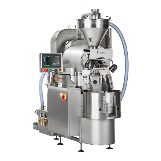
Page 8: Major Components, Assembled
S15 Assembly and Installation Guide Major Components, Assembled The core pieces of Loring coffee-roasting equipment are the coffee roaster itself and a Green Bean Cart that is included with the S15 roaster. A separate piece of optional equipment, the Destoner, is described in a separate manual. -
Page 9: Back View, Components, As Shipped
Back Left View Back 1008286 Rev B Loring Smart Roast Proprietary – This document is controlled by Page 9 of 50 Document Control. By printing this document, it will become a “Reference” copy. Users are responsible for verifying that it is the latest revision available. - Page 10 45-Degree Vent Kit Back Page 10 of 50 Loring Smart Roast Proprietary – This document is controlled by 1008286 Rev B Document Control. By printing this document, it will become a “Reference” copy. Users are responsible for verifying that it is the latest revision available.
-
Page 11: Notes For Unpacking
Bean Hopper Vacuum Hose, and food-grade anti-seize compound to prevent fasteners from seizing during assembly. 1008286 Rev B Loring Smart Roast Proprietary – This document is controlled by Page 11 of 50 Document Control. By printing this document, it will become a “Reference” copy. -
Page 12: Uncrate The Roaster
Cyclone Vacuum Tube (attached to crate wall} Page 12 of 50 Loring Smart Roast Proprietary – This document is controlled by 1008286 Rev B Document Control. By printing this document, it will become a “Reference” copy. Users are responsible for verifying that it is the latest revision available. - Page 13 Green Bean Hopper Lid Remove wood screws and move out of the crate. 1008286 Rev B Loring Smart Roast Proprietary – This document is controlled by Page 13 of 50 Document Control. By printing this document, it will become a “Reference” copy.
- Page 14 Cyclone (leave this until the roaster has feet attached and moved to assembly area). Page 14 of 50 Loring Smart Roast Proprietary – This document is controlled by 1008286 Rev B Document Control. By printing this document, it will become a “Reference” copy.
-
Page 15: Attach Roaster Feet
Foot Block in the far left corner. A socket extension may be needed. Lag bolt 1008286 Rev B Loring Smart Roast Proprietary – This document is controlled by Page 15 of 50 Document Control. By printing this document, it will become a “Reference” copy. - Page 16 WARNING: Do not use the outer ends of the roaster as lift points. Page 16 of 50 Loring Smart Roast Proprietary – This document is controlled by 1008286 Rev B Document Control. By printing this document, it will become a “Reference” copy.
- Page 17 Access Panel Front 1008286 Rev B Loring Smart Roast Proprietary – This document is controlled by Page 17 of 50 Document Control. By printing this document, it will become a “Reference” copy. Users are responsible for verifying that it is the latest revision available.
-
Page 18: Assemble The Roaster
Page 18 of 50 Loring Smart Roast Proprietary – This document is controlled by 1008286 Rev B Document Control. By printing this document, it will become a “Reference” copy. Users are responsible for verifying that it is the latest revision available. - Page 19 Cart. This end has an operable clip with an exposed surface inside the Vacuum Hose. This end is detachable. 1008286 Rev B Loring Smart Roast Proprietary – This document is controlled by Page 19 of 50 Document Control. By printing this document, it will become a “Reference” copy.
- Page 20 Clamp Front Page 20 of 50 Loring Smart Roast Proprietary – This document is controlled by 1008286 Rev B Document Control. By printing this document, it will become a “Reference” copy. Users are responsible for verifying that it is the latest revision available.
-
Page 21: Attach Vacuum Tube
Top View Front 1008286 Rev B Loring Smart Roast Proprietary – This document is controlled by Page 21 of 50 Document Control. By printing this document, it will become a “Reference” copy. Users are responsible for verifying that it is the latest revision available. - Page 22 Vacuum Tube Connection Page 22 of 50 Loring Smart Roast Proprietary – This document is controlled by 1008286 Rev B Document Control. By printing this document, it will become a “Reference” copy. Users are responsible for verifying that it is the latest revision available.
- Page 23 Green Bean Hopper Lid. The Vacuum Tube must always be supported by the Vacuum Tube Flange Plate. 1008286 Rev B Loring Smart Roast Proprietary – This document is controlled by Page 23 of 50 Document Control. By printing this document, it will become a “Reference” copy.
-
Page 24: Attach The Cyclone
Page 24 of 50 Loring Smart Roast Proprietary – This document is controlled by 1008286 Rev B Document Control. By printing this document, it will become a “Reference” copy. - Page 25 CAUTION: Use care when inserting studs on Cyclone’s Circulation Fan Connection into the flange of the Circulation Fan Housing. 1008286 Rev B Loring Smart Roast Proprietary – This document is controlled by Page 25 of 50 Document Control. By printing this document, it will become a “Reference” copy.
-
Page 26: Attach Purge Gate Air Cylinder
Assembly Bracket Page 26 of 50 Loring Smart Roast Proprietary – This document is controlled by 1008286 Rev B Document Control. By printing this document, it will become a “Reference” copy. Users are responsible for verifying that it is the latest revision available. -
Page 27: Attach Gas Mixer Line
Utility Tray. Keep these fasteners to re-install the Utility Tray covers later. 1008286 Rev B Loring Smart Roast Proprietary – This document is controlled by Page 27 of 50 Document Control. By printing this document, it will become a “Reference” copy. -
Page 28: Secure Cyclone Fasteners
Use anti-seize compound on fastener threads. Page 28 of 50 Loring Smart Roast Proprietary – This document is controlled by 1008286 Rev B Document Control. By printing this document, it will become a “Reference” copy. -
Page 29: Water Line (Chaff Quench Hose)
1008286 Rev B Loring Smart Roast Proprietary – This document is controlled by Page 29 of 50 Document Control. By printing this document, it will become a “Reference” copy. -
Page 30: Connect The Ignition Wire
Gas supply line pipe union connection Page 30 of 50 Loring Smart Roast Proprietary – This document is controlled by 1008286 Rev B Document Control. By printing this document, it will become a “Reference” copy. Users are responsible for verifying that it is the latest revision available. -
Page 31: Burner Control Unit (Bcu) Ignition
Utility Tray Electrical Cabinet (UTEC) as shown in the diagram in the next page. 1008286 Rev B Loring Smart Roast Proprietary – This document is controlled by Page 31 of 50 Document Control. By printing this document, it will become a “Reference” copy. - Page 32 5. Locate the ignition wire terminal and plug the ignition wire boot 4 on it. Page 32 of 50 Loring Smart Roast Proprietary – This document is controlled by 1008286 Rev B Document Control. By printing this document, it will become a “Reference” copy.
-
Page 33: Direct Spark Ignition (Dsi)
Cabinet (UTEC) 1008286 Rev B Loring Smart Roast Proprietary – This document is controlled by Page 33 of 50 Document Control. By printing this document, it will become a “Reference” copy. Users are responsible for verifying that it is the latest revision available. - Page 34 Utility Tray Electrical Cabinet (UTEC) Page 34 of 50 Loring Smart Roast Proprietary – This document is controlled by 1008286 Rev B Document Control. By printing this document, it will become a “Reference” copy. Users are responsible for verifying that it is the latest revision available.
- Page 35 S15 Assembly and Installation Guide Connect the DSI wire inside the Utility Tray Electrical Cabinet. 1008286 Rev B Loring Smart Roast Proprietary – This document is controlled by Page 35 of 50 Document Control. By printing this document, it will become a “Reference” copy.
-
Page 36: Install The Thermocouples
It is important to not omit this step as the thermocouple lines can be damaged by heat resulting in roaster malfunction. Page 36 of 50 Loring Smart Roast Proprietary – This document is controlled by 1008286 Rev B Document Control. By printing this document, it will become a “Reference” copy. -
Page 37: Complete The Cyclone Installation
• Chaff Barrel 1008286 Rev B Loring Smart Roast Proprietary – This document is controlled by Page 37 of 50 Document Control. By printing this document, it will become a “Reference” copy. Users are responsible for verifying that it is the latest revision available. -
Page 38: Final Roaster Assembly
Blower. The blower is heavy. It will need to be turned upside down to shake items out of it. Page 38 of 50 Loring Smart Roast Proprietary – This document is controlled by 1008286 Rev B Document Control. By printing this document, it will become a “Reference” copy. - Page 39 Auto Hopper Blower 1008286 Rev B Loring Smart Roast Proprietary – This document is controlled by Page 39 of 50 Document Control. By printing this document, it will become a “Reference” copy. Users are responsible for verifying that it is the latest revision available.
-
Page 40: Move Roaster To Final Location
Chaff Barrel Clamp Front Right View, fully assembled Page 40 of 50 Loring Smart Roast Proprietary – This document is controlled by 1008286 Rev B Document Control. By printing this document, it will become a “Reference” copy. Users are responsible for verifying that it is the latest revision available. -
Page 41: Adjust The Operator's Console
The following diagrams so how to carry out adjustments to the Articulating Arm. 1008286 Rev B Loring Smart Roast Proprietary – This document is controlled by Page 41 of 50 Document Control. By printing this document, it will become a “Reference” copy. -
Page 42: Chaff Barrel
Obtain a compressed air supply that meets the specifications listed in the Pre-Installation and Site Preparation Guide. Complete this task prior to the final site commissioning visit from the Loring Field Service Technician. Contact Loring for guidance on selecting and ordering suitable equipment. -
Page 43: Install The Roaster
However, final IP configuration cannot be done until the roaster is powered on for the first time by a Loring Field Service Technician, during site commissioning. Note: The roaster will operate without being connected to a computer network, but this will limit technical support, and will prevent the roaster from sending Roast Data reports at the end of each roast, as well as Alarm Status and Alarm History email reports. -
Page 44: Air, Gas, And Water Connections
Front Water Page 44 of 50 Loring Smart Roast Proprietary – This document is controlled by 1008286 Rev B Document Control. By printing this document, it will become a “Reference” copy. Users are responsible for verifying that it is the latest revision available. -
Page 45: Hot Air Exhaust Vent Connection
Back Front 1008286 Rev B Loring Smart Roast Proprietary – This document is controlled by Page 45 of 50 Document Control. By printing this document, it will become a “Reference” copy. Users are responsible for verifying that it is the latest revision available. -
Page 46: Cooling Air Exhaust Vent Connection
Back Front Page 46 of 50 Loring Smart Roast Proprietary – This document is controlled by 1008286 Rev B Document Control. By printing this document, it will become a “Reference” copy. Users are responsible for verifying that it is the latest revision available. -
Page 47: Electrical And Network Connections
Network (LAN) Inlet 1008286 Rev B Loring Smart Roast Proprietary – This document is controlled by Page 47 of 50 Document Control. By printing this document, it will become a “Reference” copy. Users are responsible for verifying that it is the latest revision available. -
Page 48: Next Steps
Next Steps After all assembly and installation tasks described in this manual have been completed, the customer should contact Loring to schedule a site visit and system commissioning from an authorized Loring Field Service Technician. System commissioning includes on site customer training. - Page 49 S15 Assembly and Installation Guide This page intentionally left blank. 1008286 Rev B Loring Smart Roast Proprietary – This document is controlled by Page 49 of 50 Document Control. By printing this document, it will become a “Reference” copy. Users are responsible for verifying that it is the latest revision available.
-
Page 50: Manufacturer Contact Information
(707) 526-7215 ext. 217 support@loring.com Page 50 of 50 Loring Smart Roast Proprietary – This document is controlled by 1008286 Rev B Document Control. By printing this document, it will become a “Reference” copy. Users are responsible for verifying that it is the latest revision available.
Need help?
Do you have a question about the Falcon S15 and is the answer not in the manual?
Questions and answers