Xylem McDonnell & Miller PSE-800-M Low Water Cut-off Application, Installation, Operation, And Maintenance Manual
Hide thumbs
Also See for McDonnell & Miller PSE-800-M Low Water Cut-off:
- Instruction manual (8 pages)
Table of Contents
Advertisement
Quick Links
Advertisement
Table of Contents

Related Manuals for Xylem McDonnell & Miller PSE-800-M Low Water Cut-off


Summary of Contents for Xylem McDonnell & Miller PSE-800-M Low Water Cut-off
- Page 1 Installation, Operation, and Maintenance Manual PSE-800-M Low Water Cut-off...
-
Page 3: Table Of Contents
Table of Contents Table of Contents Introduction and Safety.........................2 Introduction............................2 Safety..............................2 Safety terminology and symbols....................2 User safety............................3 Product warranty..........................4 Product Description..........................5 General description..........................5 Operational specifications.........................5 Electrical specifications........................6 Installation...............................7 Determine location for the probe installation.................7 Install the probe...........................7 Install the control housing........................8 Wire the probe to the control housing.....................8 Control to boiler wiring........................9 Electrical conduit connections......................9... -
Page 4: Introduction And Safety
This includes any modification to the equipment or use of parts not provided by Xylem. If there is a question regarding the intended use of the equipment, please contact a Xylem representative before proceeding. -
Page 5: User Safety
Introduction and Safety Hazard levels Hazard level Indication A hazardous situation which, if not avoided, will result in DANGER: death or serious injury A hazardous situation which, if not avoided, could result WARNING: in death or serious injury A hazardous situation which, if not avoided, could result CAUTION: in minor or moderate injury •... -
Page 6: Product Warranty
Product warranty Coverage Xylem undertakes to remedy defects in products from Xylem under these conditions: • The faults are due to defects in design, materials, or workmanship. • The faults are reported to an local sales and service representative within the warranty period. -
Page 7: Product Description
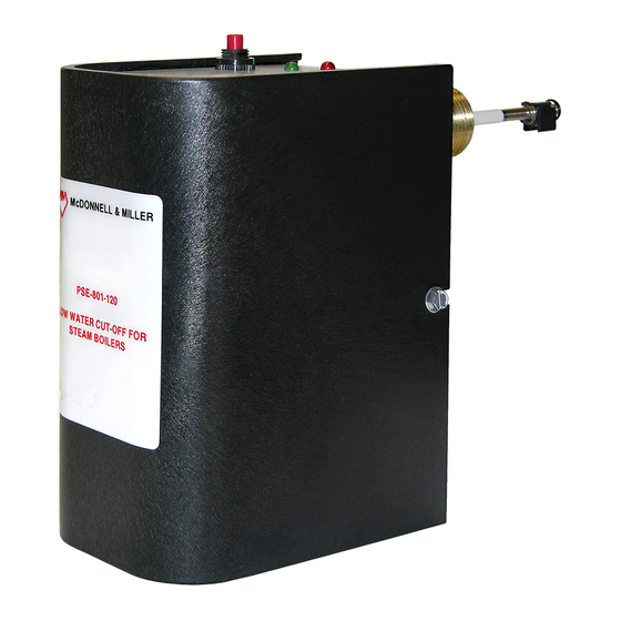
Product Description Product Description General description Description The probe is a manual reset low water cut-off control. The control unit has a red LED light to alert personnel to a low water condition and a green LED to indicate normal operation. Lockout delay When a low water condition occurs, the burner turns off and the red LED begins to blink. -
Page 8: Electrical Specifications
Product Description Humidity 85% non-condensing Probe specifications Maximum steam pressure: 15 psi (1.0 kg/cm Probe dimensions in inches (mm) 3/4 NPT 1.31 1.56 2.13 (33) (40) (54) Figure 2: Standard probe 3/4 NPT 1.31 3.06 1.56 (33) (78) (40) Figure 3: “U” probe Electrical specifications Ratings Model... -
Page 9: Installation
Installation Installation Determine location for the probe installation DANGER: Electrical hazard sufficient to kill. Always disconnect and lock out the power before you service the unit. NOTICE: • Low water cut-off must be installed in series with all other limit and operating controls on the boiler. -
Page 10: Install The Control Housing
Installation Install the control housing 1. Loosen the screws that secure the cover (5) to the control housing about 1–1/2 turns. Remove cover. 2. Loosen the probe mounting screws (4) 1–1/2 turns or 1/8” (3 mm). 3. Slip the control housing (6) over the two screws at a 20° angle. 4. -
Page 11: Control To Boiler Wiring
Installation Control to boiler wiring Warning: • Fire hazard. Electrical wiring must have a rating of 167ºF (75ºC) if the liquid exceeds 180ºF (82ºC). • When installing jumper wire make sure you are not introducing a second voltage source into the burner circuit and thereby bypassing other safety, limit, and operating controls. Select a wiring method after reviewing the wiring diagrams and notes. -
Page 12: Option A Wiring
Installation Option A wiring Voltage of the new manual reset LWCO is the same as the existing auto reset LWCO 1. Remove existing wire from terminal B of existing Auto Reset LWCO and connect to terminal B of new Manual Reset LWCO. 2. -
Page 13: Option C Wiring
Installation Existing wiring to boiler New wiring to boiler N H C W B (L1) (L1) (L1) (L1) 120 VAC 120 VAC 1. Factory jumper bar 2. Boiler connections 3. Service switch _ _ _ _ Dashed lines indicate existing wires. _____ Solid lines indicate new wires. - Page 14 Installation Existing wiring to boiler New wiring to boiler N H C W B 1. Factory jumper bar 2. To burner 3. Neutral 4. Hot _ _ _ _ Dashed lines indicate existing wires. _____ Solid lines indicate new wires. PSE-800-M Low Water Cut-off Installation, Operation, and Maintenance Manual...
-
Page 15: Commissioning, Startup, Operation, And Shutdown
Commissioning, Startup, Operation, and Shutdown Commissioning, Startup, Operation, and Shutdown Start up the boiler 1. Before filling the system, turn on the electric power to the boiler. a) Upon initial power up, the green and red lights will flash simultaneously four times. b) The green light will turn on and the red light will begin to flash. -
Page 16: Maintenance
Maintenance Maintenance Maintenance schedule Warning: • Maintenance and service must be performed by skilled and qualified personnel only. • Replace probe when PFA insulator is cracked or worn or probe is loose. • Test the low water cut-off annually. • Remove and inspect the self-cleaning probe every five years. •... -
Page 17: Troubleshooting
Troubleshooting Troubleshooting Probe fails to operate Perform the following diagnostic checks if the probe fails to operate as required: 1. Check that the water level in the boiler is at or above the level of the probe. 2. Recheck all wiring to ensure proper connections as specified in the wiring diagrams of the boiler manufacturer or in this instruction manual. - Page 20 For more information on how Xylem can help you, go to xyleminc.com Xylem Inc. Visit our Web site for the latest version of this document and more information 8200 N.
Need help?
Do you have a question about the McDonnell & Miller PSE-800-M Low Water Cut-off and is the answer not in the manual?
Questions and answers