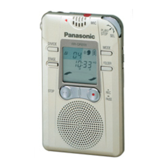
Panasonic RR-QR100 Service Manual
Ir recorder
Hide thumbs
Also See for RR-QR100:
- Operating instructions manual (9 pages) ,
- Operating instructions manual (26 pages)

Related Manuals for Panasonic RR-QR100


Summary of Contents for Panasonic RR-QR100
- Page 1 ORDER NO. AD0107131C2 IC Recorder RR-QR100 / RR-QR200 Colour (S)....Silver Type Areas (E)....Europe. SPECIFICATIONS Specifications...
- Page 2 Batteries (Panasonic alkaline batteries): Playback; About 15 hours Recording; About 30 hours Available recording time: LP (Lnog play); 100min.(RR-QR100) / 200min.(RR- QR200) SP (Standard play); 31min.(RR-QR100) / 65min.(RR-QR200) HQ (High quality); 15min.(RR-QR100) / 32min.(RR-QR200) Folders: 4 (A,B,C,D) Note: The battery life may be less depending on the operating conditions.
- Page 3 the major printed circuit boards and replacing the main components. - For reassembly after operation checks or replacement, reverse the respective procedures. Special reassembly procedures are described only when required. 2.1. Cheking for the P.C.B. (A side) - Check the P.C.B. (A side) as shown below.
- Page 4 2.2. Cheking for the P.C.B. (B side) - Follow the (Step 1) - (Step 5) of item 2.1. - Check the P.C.B. (B side) as shown below.
- Page 6 2.3. Replacement for the speaker - Follow the (Step 1) - (Step 5) of item 2.1. - Follow the (Step 1) - (Step 3) of item 2.2.
- Page 7 2.4. Replacement for the LCD - Follow the (Step 1) - (Step 5) of item 2.1. - Follow the (Step 1) - (Step 3) of item 2.2. 3. Type Illustration of IC’s, Transistors and Diodes 3.1. RR-QR100 3.2. RR-QR200...
- Page 8 When replacing any of components, use only manufacturer’s specified parts. - Signal lines : Source signal (ANALOG) line : Source signal (DIGITAL) line : Positive voltage line 4.2. Schematic Diagram (RR-QR100) 4.3. Schematic Diagram (RR-QR200) 5. Printed Circuit Board Diagram (RR-QR100)
- Page 9 6. Printed Circuit Board Diagram (RR-QR200) 7. Block Diagram 7.1. RR-QR100 7.2. RR-QR200 8. Operation Check Mode This unit is equipped with the functions to check it to record or playback usually and the display of LCD. - Caution! When the checking operation is performed, all recorded data will be cleared.
- Page 10 2. Release the HOLD mode. 3. Check the display of LCD is displayed as shown below. Fig.2-2. Fig.2-2. 4. Press the MODE switch. 5. Check the display of LCD is displayed as shown below. Fig.2-3. Fig.2-3.
- Page 11 6. Press the FOLDER switch. 7. Check the display of LCD is displayed as shown below. Fig.2-4. Fig.2-4. 8. Press the REC switch and record a voice. Fig.2-5. Fig.2-5.
- Page 12 9. Press the STOP switch. 10. The display of LCD as shown below is 10 seconds the recording. Fig.2-6. Fig.2-6. 11. Press the ERACE switch to playback. 12. In playback, check the display of LCD is displayed as shown below. (The display of LCD is difference from the shown below by the time of recording.) Fig.2-7.
- Page 13 14. When the playback of 10 seconds recording is finished, the display of LCD is displayed as shown below. Fig.2-8. Fig.2-8. 15. Pressing the PLAY/STOP and select dial continuously. The format is started. Note: The format is started once, all recorded data in the Flash Memory will be cleared.
- Page 14 16. Operation Check Mode is canceled when the battery cover is opened. 9. Troubleshooting 9.1. Unit won´t play -Checking the Analog System-...
- Page 17 Take the steps outlined in <2> Check the Data Transmission Between IC 4 and IC 9 of 9.4. Confirm that the pulse characteristics change in IC 9 pin 22 (/CE) and pin 3 (R/B) <RR-QR100> / pin 7 (R/B) <RR-QR200> during deleting.
- Page 20 9.4. Unit won´t record -Checking the Digital System- <1> Check the Data Transmission Between IC 2 and IC 4. 1. Checking IC 2 Pulse Cycle and Clock Frequency. Categories Pin No. Mode to be Measured Pulse 40(/CS) 8 ms 16 ms 8 ms frequency*1 Clock...
- Page 21 22(/CE) 64 ms 128 ms 409.6 ms frequency*1 Clock 20(SC) 500 kHz 500 kHz 500 kHz frequency (approx.) (approx.) (approx.) (RR-QR100) Clock 8(SC) 500 kHz 500 kHz 500 kHz frequency (approx.) (approx.) (approx.) (RR-QR200) 9.5. Unit won´t play -Checking the Digital System- <1>...
- Page 22 Mark Function Division COM3 LCD segment signal outputs ~ COM0 VLC3 — LCD reference voltage input termnal (connected to DGND) VLC2 LCD reference voltage input terminal VLC1 — LCD reference voltage input terminal Power supply terminal (3.3V) OSC2 — Not used, open. OSC1 Main system clock input (f= 8MHz)
- Page 23 input Mark Function Division LSI chip signal output Flash-Memory chip output command/data ratch output — Not used, open. /RST RU Reset signal input LSI reset output Data command select signal output Beep output Clock select signal output Flash-Memory command data output IRQ0 VAS voice detection results input...
- Page 24 Mark Function Division Mic. sensitivity "H" set up output Playback signal output (H: Playback) 65,66 P76,P77 — Not used, open. C/F data command BUS D7 / ~ / SEG25 — Not used, open. SEG24 — Not used, open. SEG23 — Not used, open.
- Page 25 - All parts are supplied by MESA. Ref. No. Part No. Part Name & Description Remarks RGV0231-H KNOB,HOLD RHQ0051-K SCREW RKW0592-Q PANEL,LCD RYK0973H-H REAR CABINET ASS’Y (RR-QR100) RYK0973J-H REAR CABINET ASS’Y (RR-QR200) XTNR2+5CFN SCREW RHQ0060-N SCREW RJC40017 BATTERY TERMINAL(+) RJC80019 BATTERY TERMINAL(-) RJM0019...
- Page 26 F1H1A105A028 C37,38 F3H0J227A001 6.3V 220U ECUE1H332KBQ 50V 3300P F1G1H332A446 ECST0JY106RR 6.3V 10U ECST0JY106R ECUVNC104KBV 16V 0.1U ECUV1H151JCV 50V 150P (RR-QR100) ECUE1H151JCQ 50V 150P ECJ0EC1H151J (RR-QR200) C44,45 ECUVNC104KBV 16V 0.1U ECUE1H120JCQ 50V 12P ECUVNC104KBV 16V 0.1U ECUENA104KBQ 10V 0.1U F1G1A104A014 ECUV1H102KBV...
- Page 27 IC,SYSTEM CONTROL/LCD DRIVE (RR-QR200) TC7W74FUT2L IC,D-TYPE FLIP FLOP XC61CN2002MR IC,RESET C0EBD0000051 TC7WH157FUTL IC,SWITCHING C0JBAR000191 XC6368B101MR IC,DC-DC CONVERTER C0DBAZZ00032 HN29W6411TT IC,64M bit MEMORY C3FBPC000005 (RR-QR100) C3FBQC000004 IC,128M bit MEMORY (RR-QR200) IC10,11 TC7WH157FUTL IC,SWITCHING C0JBAR000191 IC12 XC61CN1802MR IC,RESET IC13 NJM2107FTE1 IC,MIC AMP C0ABAB000040...
- Page 28 1/16W 100K ERJ2GEJ104X 1/4W 100K ERJ2RMJ104X ERJ2GEJ102X 1/4W 1K ERJ2RMJ102X ERJ2GED105X 1/4W 1M ERJ2RKD105X ERJ3RED434V 1/16W 430K ERJ2GEJ105X 1/4W 1M D0GA105JA001 (RR-QR100) ERJ2GEJ222X 1/4W 2.2K ERJ2RMJ222X (RR-QR200) ERJ3GEYJ102V 1/16W 1K ERJ3GEYJ102Z ERJ2GEJ100X 1/4W 10 ERJ2RMJ100X ERJ2GEJ103X 1/4W 10K ERJ2RMJ103X ERJ2GEJ154X...
- Page 29 Ref. No. Part No. Part Name & Description Remarks ERJ2GEJ103X 1/4W 10K ERJ2RMJ103X EVQPLMA15 SW,DIVIDE EVQPLMA15 SW,ERASE RFKDNS300R-S SW,JOG DIAL ASS’Y EVQPLMA15 SW,REC/PAUSE RSS2A010-1A SW,HOLD K0D112B00071 RSH1A039-A SW,B.COVER CLOSE DET. K0L1BA000037 EVQPLMA15 SW,FOLDER EVQPLMA15 SW,MODE EVQPLMA15 SW,STOP EVUTUHB07C54 VR,VOLUME RSXY8M19M01T CERAMIC OSC H2D819400001 RSXC32K7L04T...
- Page 30 13. Packaging...
- Page 31 K010700000YH...
- Page 32 (SIDE : A) IC14 IC13 IC16 HOLD Q10 B SPEAKER 28mm(1 ), 8 32in. 2AAA SIZE (R03/LR03,UM-4) BATTERIES 3V 2152D (REP3206B-M) RR-QR200(E) MAIN P.C.B.
- Page 33 (SIDE : B) (REC) (PLAY/STOP, SEL) EARPHONE MODE DIVIDE FOLDER ERASE REC/ PAUSE STOP IC12 IC10 IC11 RR-QR200(E) MAIN P.C.B.
- Page 34 (SIDE : A) IC14 IC13 IC16 HOLD Q10 B SPEAKER 28mm(1 ), 8 32in. 2AAA SIZE (R03/LR03,UM-4) BATTERIES 3V 2152C (REP3206A-M) RR-QR100(E) MAIN P.C.B.
- Page 35 (SIDE : B) (REC) (PLAY/STOP, SEL) EARPHONE MODE DIVIDE FOLDER ERASE REC/ PAUSE STOP IC12 IC10 IC11 RR-QR100(E) MAIN P.C.B.
- Page 36 :POSITIVE VOLTAGE LINE :SOURCE SIGNAL(ANALOG) LINE 2SB1295-6-TB POWER SUPPLY MA735TX MA735TX 3.3V 3.3V 2 AAA SIZE (R03/LR03,UM-4) 2.7V BATTERIES 3V 2SK1958T1 POWER SUPPLY 1.2V 3.3V 2.8V CONTROL 2.8V XC6368B101MR DC-DC CONVERTER CL170HRCDT (REC) 1.5K 0.3V 2.8V 3300P 2SD1119RTX 3.3V SWITCHING 1.5K (0V) (0V)
- Page 37 :POSITIVE VOLTAGE LINE :SOURCE SIGNAL(ANALOG) LINE :SOURCE SIGNAL(DIGITAL) LINE 3.3V TC7W74FUT2L TC7WU04FUT2L (8.19MHz) D-TYPE TC7WH157FUTL TRIPLE INVERTER FLIP FLOP SWITCHING 1.7V 3.3V 1.7V 3.3V 1.7V 3.3V 1.6V 3.3V 1.3V 1.7V 1.6V 3.3V 3.3V 1.7V 3.3V 1.7V SELECT (10.24MHz) 1.7V 1.7V 14 13 12 11 10 9 8 7 6 5 4 3 2 1 DTC144TETL SWITCHING...
- Page 38 :POSITIVE VOLTAGE LINE :SOURCE SIGNAL(DIGITAL) LINE 3.3V LCD1(RSL5243-T) LCD DISPLAY 5 6 7 8 9 10 11 12 13 14 15 16 17 18 19 20 21 22 23 24 A B C D E F G H I J K L M N O P Q R S T U V W X 100K 1.6V COM3...
- Page 39 2.8V REC MODE SELECT(LP) (1.3V) (1.3V) 3.3V 2SK1958T1 2SK1958T1 150K SWITCHING 1.7V 1.7V SWITCHING 1.7V 2SK1958T1 REC MODE SELECT 1.7V (HQ) 3.5mm (1/8 IN.) 6.8K 6.8K PLUG IN POWER 2.2M (3.3V) MA111TX 4700P 4700P DTC144TUA106 SWITCHING(MIC) RR-QR100(E) MAIN SCHEMATIC DIAGRAM...
- Page 40 1.7V DASD 1.7V A OUT L SIOCK 29 30 31 32 33 34 35 36 37 38 39 40 41 42 3.3V XC61CN2002MR RESET VOUT 3.3V 3.3V 3.3V 120K 100K (HOLD) 330K 120K 100K (PLAY/ STOP,SEL) RR-QR100(E) MAIN SCHEMATIC DIAGRAM...
- Page 41 I/O 3 TC7WH157FUTL TC7WH157FUTL SWITCHING SWITCHING 3.3V 3.3V 3.3V 3.3V 3.3V 3.3V 3.3V 1.2V I/O 4 1.2V I/O 5 1.2V I/O 6 1.2V SELECT SELECT I/O 7 3.3V / WE 3.3V 3.3V / CE 100K 3.3V RR-QR100(E) MAIN SCHEMATIC DIAGRAM...
- Page 42 MN101C16ACD1 XC61CN1802MR HN29W6411TT NJM2107FTE1 TC7WH157FUTL XC61CN2002MR XC6368B101MR TC7W74FUT2L ..TC7WU04FUT2L ....C0ABZA000033 ..
- Page 43 MN101C16ACE XC61CN1802MR C3FBQC000004 NJM2107FTE1 TC7WH157FUTL XC61CN2002MR XC6368B101MR TC7W74FUT2L ..TC7WU04FUT2L ....C0ABZA000033 ..
- Page 44 > <...
- Page 45 IC14 EARPHONE POWER AMP XC61CN2002MR VOUT2 RESET P.SUPPLY CONT. (REC) TC7WU04FUT2L TC7W157FUTL (8.19MHz) POWER TRIPLE SWITCHING SUPPLY LCD DISPLAY INVERTER (11.06MHz) XC6368B101MR POWER TC7W74FUT2L SUPPLY R03/LR03, DC-DC CONV. AAA,UM-4 D-TYPE BATTERIES FLIP FLOP RR-QR100(E) SWITCH- POWER SUPPLY MAIN BLOCK DIAGRAM...
- Page 46 TC7WH157FUTL C3FBQC000004 Notes IC10,11 SC,/WE XC61CN1802MR SWITCHING Signal line : Source signal(analog) 128M bit MEMORY IC12 /CDE,/RES, Signal line : Source signal(digital) R/B,/CE,/OE RESET O0~7 Q25,26 PO1,O2, IRQ4 O4,05,31, NJM2107FTE1 REC MODE D0~7 D0~7 IC13 L IN SELECT PA4~7, MIC AMP EMP,MID,FUL, KEY SW ML2301GA...
Need help?
Do you have a question about the RR-QR100 and is the answer not in the manual?
Questions and answers