Table of Contents
Advertisement
Advertisement
Table of Contents

Related Manuals for Panasonic KW1M-H


Summary of Contents for Panasonic KW1M-H
- Page 2 【KW1M-H (SD card type)】 Basic setting to measure by Eco-POWER METER When wiring the main unit and the current transformer (CT) and setting the basic setting after power on, you can measure the power The basic setting of MODE1 is necessary to measure.
- Page 3 Copyright and trademark ● Panasonic Electric Works SUNX Co., Ltd. owns the copyright of this manual. ● We stiffly refuse the reproduction of without permission from this manual. ●Modbus Protocol is a communication protocol that the Modicon Inc.developed for PLC.
- Page 4 Introduction Thank you very much indeed for purchasing ‘KW1M-H Eco-POWER METER’. In this manual, we explain the usage of ‘KW1M-H Eco-POWER METER’ in detail. Please use it correctly after understanding the content enough.
-
Page 5: Table Of Contents
Table of Contents Chapter 1 Unit’s Features and Structure ....................1 1.1 Unit’s Name and Model Numbers ......................1 1.1.1 Main unit ............................1 1.1.2 Option ............................. 1 1.1.3 Tool ..............................2 1.1.4 Firmware ............................2 1.2 Measurement items ..........................3 Chapter 2 Parts Name and Working ...................... - Page 6 Chapter 6 Display of each Value ......................42 6.1 Working of Monitor Display ........................42 6.2 Power Monitoring mode ......................... 45 6.2.1 Integrated electric power ......................45 6.2.2 Instantaneous electric power ......................45 6.2.3 Current ............................46 6.2.4 Voltage ............................46 6.2.5 Electricity Charge .........................
- Page 7 Cautions before using ■ Installation environment ◇Do not use the Unit in the following environments. ・Where the unit will be exposed to direct sunlight and where the ambient temperature is outside the range of -10 to 50 °C. ・Where the ambient humidity is outside the range of 30 to 85 % RH (at 20℃, non-condensing) and where condensation might occur by sudden temperature changes ・Where inflammable or corrosive gas might be produced ・Where the unit will be exposed to excessive airborne dust or metal particles...
-
Page 8: Power Supply
■ Power supply ・Connect a breaker to the voltage input part for safety reasons and to protect the device. The breaker that connects to the voltage input part must arrange at the position easily reached, and display shows it is the breaker of the equipment. ・Do not turn on the power supply or input until all wiring is completed. -
Page 10: Chapter 1 Unit's Features And Structure
KW1M-H Eco-POWER METER Chapter 1 Unit’s Features and Structure KW1M-H Eco-POWER METER is the suitable size wattmeter for installing in a control board. It measures electrical power, voltage, current and so on using AC voltage and AC current input. It also works ad an hour meter, which is measured power-on or power-off time. -
Page 11: Tool
Download from our website. KW View from Eco-POWER METER Free of charge Note) Members registration is required to download. 1.1.4 Firmware For using the additional functions of KW1M-H Functions Supported version - 600A CT input Ver.1.05 or more - Simple demand measurement Ver.1.10 or more... -
Page 12: Measurement Items
KW1M-H Eco-POWER METER 1.2 Measurement items Item Unit Data range (Display) kWh/ 0.00 to 9999.99MWh Integrated electric power (Active) (9-digit display) 0.00 to 9999999.99kWh Instantaneous electric power (Active) 0.00 to 9999.99 R-current Current S-current 0.0 to 6000.0 T-current R(RS)-voltage Voltage S(RT)-voltage 0.0 to 9999.9... -
Page 13: Chapter 2 Parts Name And Working
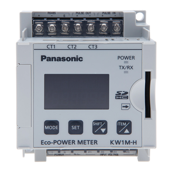
KW1M-H Eco-POWER METER Chapter 2 Parts Name and Working 2.1 Parts Names ①MODE indicator Lighting when mode setting ②LOCK indicator Lighting while in lock mode ③OP. output indicator Lighting when pulse output ④Mode display Display mode in setting and measurement item with 16-seg ⑤Display each value... -
Page 14: Chapter 3 Wiring
KW1M-H Eco-POWER METER Chapter 3 Wiring Be sure to wire correctly according to the terminal arrangement and wiring diagrams. After completing wiring, be sure to attach the terminal cover for safety reasons. 3.1 Terminal arrangement Function ① Power supply ②... -
Page 15: Wiring Diagrams
KW1M-H Eco-POWER METER 3.2 Wiring Diagrams Please connect a breaker (3 to 15A) to the voltage input part for safety reasons and to protect the device. Grounding the secondary side of VT (Voltage transformer) and CT (Current transformer) is not necessary with low-voltage circuit. -
Page 16: How To Attach The Current Transformer (Ct)
KW1M-H Eco-POWER METER ◆When measuring a load with exceed input voltage Voltage transformer (VT) is needed when you measure a load with over rated input voltage (440V). Use VT, those secondary rating is 110V. Grounding the secondary side of VT and CT is not necessary with low-voltage circuit. - Page 17 KW1M-H Eco-POWER METER ◇To connect CT with secondary side current 5A How to set for measuring by combination with CT (secondary side current 5A) (1) Select 5A at CT type setting mode (CT-T). (2) Set the primary current of measured CT (secondary side current 5A) at primary side current of CT setting mode (CT-1).
-
Page 18: For Input Connection
KW1M-H Eco-POWER METER 3.4 For input connection ・Contact input Use highly reliable metal plated contacts. Since the contact’s bounce time leads directly to error in the count value, use contacts with as short a bounce time as possible. In general, select 30Hz for max. -
Page 19: For Output Connection
KW1M-H Eco-POWER METER 3.5 For Output connection ・Since the transistor output is insulated from the internal circuit by a photo-coupler, it can be used both as a plus common and minus common. Eco-POWER METER Eco-POWER METER Plus common Pulse (+) -
Page 20: Low Voltage Directive
KW1M-H Eco-POWER METER Recommended Cable Use the transmission cables shown below for Eco-POWER METER RS485 communication system. Conductor Insulator Cable Resistance Cable Applicable cable diameter Size Material Thickness (at 20℃) HITACHI 1.25 mm KPEV-S Max. Approx. (AWG16) Max.16.8Ω/km Polyethylene ×1P 0.5 mm... -
Page 21: Chapter 4 Settings
KW1M-H Eco-POWER METER Chapter 4 Settings 4.1 Operation procedure 【Basic setting to measure】 When wiring Eco-POWER METER and CT and setting mode 1 after power on, Eco-POWER Meter can measure the electric power. In order to use the other functions, set mode2, 3 and 4 according to your use. - Page 22 KW1M-H Eco-POWER METER Mode 2…Mode for setting of each parameter for pulse measurement Mode 3…Mode for setting of each parameter for serial communication Mode 4…Mode for setting of each parameter for optional function Monitor (Display when power on) <MODE> Setting mode...
- Page 23 KW1M-H Eco-POWER METER ◆Initial value list Mode 1 Mode 2 Item Initial value Item Initial value Phase/Wire system 1P2W Max. counting 2000 speed CT type Primary side current of CT Prescale 1.000 Voltage range Power input type 1.00 Pulse type...
-
Page 24: Setting Mode Explanation
KW1M-H Eco-POWER METER 4.2 Setting Mode Explanation ■The value with under line is initial setting among each setting value. ☆Set before measurement. Press <MODE> and <SET> at a time, the setting will be initialized. 4.2.1 MODE1 (Mode for setting each parameter for power measurement.) - Page 25 KW1M-H Eco-POWER METER Unit for pulse output setting mode PL-P Mode defines unit used for pulse output. It defines the unit of integrated electric power for 1-pulse output. ・Select from 0.001/0.01/0.1/1/10/100kWh /AL-P/AL-C/AL-S/Cnt/DEM/P-THR. When one of the ‘0.001/0.01/0.1/1/10/100’ [kWh] is set, one pulse is output at reaching the setting value.
- Page 26 KW1M-H Eco-POWER METER Demand alarm setting mode3 DEM3 Mode defines the time to start demand monitoring. ・It is set the range of 1 to 30 min. (Initial 10 minutes) Ex.) When ‘10’ is set, alarm output or alarm indication ‘d’ is not occurred after 10 minutes from the demand span started.
- Page 27 KW1M-H Eco-POWER METER Mode1 Setting flow chart Monitor ↓<MODE> (MODE 1 Lighting) ↓ <SET> Phase/Wire system setting mode Press <ITEM/△><SHIFT/▽> to change Single-phase 2-wire ⇔ Single-phase 3-wire ⇔ Three-phase 3-wire ⇔ Three-phase 4-wire. 1P2W 1P3W 3P3W 3P4W ↓ <SET> CT type setting mode Press <ITEM/△><SHIFT/▽>...
- Page 28 KW1M-H Eco-POWER METER Current for time measurement setting mode Set ratio of current for time measurement using <ITEM/△> <SHIFT/▽>. If you measure the current over 50.0%F.S, set to ‘50.0’. (1.0 to 100.0) ↓ <SET> Cutoff current setting mode Set cutoff current ratio using <ITEM/△> <SHIFT/▽>.
- Page 29 KW1M-H Eco-POWER METER Stand-by alarm setting mode 1 *It is only when ‘AL-S’ is selected on unit for pulse output setting mode. Set a ratio (for the rated current) of current used for threshold value to judge stand-by power using <ITEM/△><SHIFT/▽>.
- Page 30 KW1M-H Eco-POWER METER Electricity charge setting mode Set the rate per 1kWh using <ITEM/△><SHIFT/▽>. (0.00 to 99.99 Initial: 10.00) ↓ <SET> Conversion factor setting mode Set the conversion factor per 1kWh using <ITEM/△><SHIFT/▽>. (0.000 to 9.999 Initial: 0.410) ↓ <SET>...
-
Page 31: Mode2 (Mode For Setting Of Each Parameter For Pulse Measurement)
KW1M-H Eco-POWER METER 4.2.2 MODE2 (Mode for setting of each parameter for pulse measurement) Max. counting speed setting mode *Skip when ‘P-THR’ is selected on Unit for pulse output setting mode, Mode defines max. counting speed. ・Select from 2000Hz(2kHz)/30Hz *In case of that ‘P-THR’ is set, max. counting speed is fixed to 50Hz,... - Page 32 KW1M-H Eco-POWER METER Mode2 Setting flow chart Monitor ↓<MODE> (MODE 2 Lighting) ↓ <SET> Max. counting speed setting mode *Skip when ‘P-THR’ is selected on Unit for pulse output setting mode Press <ITEM/△><SHIFT/▽> to change 2000(2kHz) ⇔ 30(30Hz). 2000(2kHz) 30(30Hz) ↓...
- Page 33 KW1M-H Eco-POWER METER Clock correction setting mode Press <ITEM/△><SHIFT/▽> to change AUTO ⇔ MANUAL ⇔ OFF. AUTO MANUAL ↓ <SET> Reference frequency setting mode *It is only when ‘MANUAL’ is selected on clock correction setting mode. Set the reference frequency using <ITEM/△><SHIFT/▽>.
-
Page 34: Mode3 (Mode For Setting Of Each Parameter For Serial Communication)
KW1M-H Eco-POWER METER 4.2.3 MODE3 (Mode for setting of each parameter for serial communication) Protocol setting mode PROT Mode defines communication protocol of main unit via serial communication (RS485). ・Select from MEWTOCOL / MODBUS(RTU). Station number setting mode Mode defines an individual station no. for each unit when two or more units communicate via serial communication (RS485). - Page 35 KW1M-H Eco-POWER METER Transmission speed setting mode Press <ITEM/△><SHIFT/▽> to change 19200 ⇔ 38400 ⇔ 57600 ⇔ 115200 ⇔ 2400 ⇔ 4800 ⇔ 9600. 19200bps 38400bps 57600bps 115200bps 2400bps 4800bps 9600bps ↓ <SET> Transmission format setting mode Press <ITEM/△><SHIFT/▽> to change 8bit-o ⇔ 7bit-n ⇔ 7bit-E ⇔ 7it-o ⇔ 8bit-n ⇔ 8bit-E.
-
Page 36: Mode4 (Mode For Setting Of Each Parameter For Optional Function)
KW1M-H Eco-POWER METER 4.2.4 MODE4 (Mode for setting of each parameter for optional function) Auto-off setting mode Display LCD turns off automatically when there is no key operation for a long time. ・Off time can be set the range of 0 to 99min. -
Page 37: Remove Sd Memory Card
KW1M-H Eco-POWER METER 4.2.5 Remove SD memory card You can remove SD memory card safety. Only when SD memory card is inserted. ・Press SD EJECT’ is displayed, and it will stop writing to SD memory card. <SET> during ‘ When ‘SD ok’ is appeared, you can remove SD memory card. - Page 38 KW1M-H Eco-POWER METER MODE4 Setting flow chart Monitor ↓<MODE> (MODE 4 Lighting) ↓ <SET> Auto-off setting mode Set auto-off time by minute using <ITEM/△><SHIFT/▽>. ( 0 to 99 ) ‘0’ should be set to turn always light on. ‘1~99’ should be set to turn light off at setting time (minute).
- Page 39 KW1M-H Eco-POWER METER Log cycle setting mode Press <ITEM/△><SHIFT/▽> to change 60 ⇔ 1 ⇔ 5 ⇔ 10 ⇔ 15 ⇔ 30. *It is not shown when ‘OFF’ is selected for T3 (type3) on saved file type setting mode. 60-minite...
-
Page 40: Chapter 5 Various Functions
KW1M-H Eco-POWER METER Chapter 5 Various Functions 5.1 LOCK mode LOCK indicator It is the mode makes all keys unable. Use when you want to fix one of the measurement displays (For all displays). In this mode, you can not input by any keys. -
Page 41: Counter Function
KW1M-H Eco-POWER METER 5.3 Counter function 5.3.1 Operation mode Maintain output hold count HOLD [Output] [Counting] possible ・・・ [Addition] n: Preset value (1) Output control is maintained after count-up completion and until reset. However counting is possible despite of count-up completion. -
Page 42: Log Data Writing Function
KW1M-H Eco-POWER METER 5.4 Log data writing function This is the function that it writes the measurement data to SD memory card. There are 3 kinds of file to write. File type 1: Instantaneous value (Saved cycle: fixed 1 hour) -
Page 43: Unit Memory
KW1M-H Eco-POWER METER <Guide for data capacity (1-day: 24 hours)> File type 1 About 4kB File type 2 About 2kB File type 3 About 210kB (Log cycle: 1 min) *Recordable data capacity is depend on the SD memory card. If there is no space to write, it will not write data after that and error is shown on the display. -
Page 44: Format For Written File
KW1M-H Eco-POWER METER 5.4.4 Format for written file Data in SD memory card is saved with the below format as csv file. The file format, which is saved by Eco-POWER METER, is fixed. <File type 1 (Instantaneous value)> Date Time... - Page 45 KW1M-H Eco-POWER METER <File type 2 (Difference value)> Date Time KW1M KW1M COM1[Unit No.01] COM1[Unit No.01] DT100 DT154 DIFFERENCE DIFFERENCE US32 ->FLT US32 ->FLT COUNT 2009/4/1 8:00:00 2009/4/1 9:00:00 2009/4/1 10:00:00 (1) Device information (Row 2) KW1M Model name (Row 3) COM1[Unit No.01]...
-
Page 46: File Name And Saved Folder
KW1M-H Eco-POWER METER 5.4.5 File name and Saved folder Files are saved in SD memory card with the below constructions. <File type 1 (Instantaneous value)> When you insert SD memory card at 13:20, April 3 2009: Folder syunji(090401_0100000_TRG).csv Data of April 1... -
Page 47: Logging Data
KW1M-H Eco-POWER METER 【File name】 sabun(090401_010000_TRG).csv Condition of saved file hour/minute/second (01:00:00) year/month/day (April 1 2009) year/month/day, hour/minute/second in file name is the data of the beginning record. Condition of saved file Recorded letter ‘File write trigger’ occurs. <File type 3 (Instantaneous detailed value)>... -
Page 48: Demand Function
KW1M-H Eco-POWER METER 5.5 Demand function (Japanese demand) A demand function is a function which presumes the average power for every 30 minutes time span, and it judges for every minute. This works demand monitoring for electric power input by CT or pulse. In order to use demand monitoring by pulse input, input pulse that meet the specifications of 8.2.3. - Page 49 KW1M-H Eco-POWER METER ◆Working at power failure and at recovery <At power failure> ・It stops the demand measurement. ・The data of present demand, demand log, monthly max. log and max.demand will be saved by the build-in battery. <At recovery> ・When it recovers within the demand span, it will start measurement of present demand again with the condition before power failure.
-
Page 50: Clock Correction Function
KW1M-H Eco-POWER METER <Estimated demand (EV)> It shows the estimated demand value at the end of demand span according to the using power from the time when demand span starts to present time. [Calculation] Power change amount Remaining Estimated Present for⊿t minutes (⊿P) -
Page 51: Chapter 6 Display Of Each Value
KW1M-H Eco-POWER METER Chapter 6 Display of each Value 6.1 Working of Monitor Display 【Shift the display mode】 It shifts displays for power monitoring mode and it for option mode by pressing <ITEM/△> and <SET>. It shifts displays for power monitoring mode and it for simple demand monitoring mode by pressing <SET>... - Page 52 KW1M-H Eco-POWER METER *1,2 Current Voltage The display is 1P2W R-current R-voltage changed according system to the phase and 1P3W R-current R-voltage, T-voltage wire system. system T-current (P1-P0) (P2-P0) 3P3W R-current, S-current, RS-voltage, RT-voltage, TS-voltage system T-current (P1-P0) (P1-P2) (P2-P0)
- Page 53 KW1M-H Eco-POWER METER 【Outline for the Working of Option Mode Display】 Calendar → Year-Month-Day Time <SHIFT/▽> Press <SHIFT/▽> to shift Year-Month-Day → Time → Year-Month-Day ・・・. ↓<ITEM/△> Monthly integrated electric power (Latest 18 months) → → → Current 1-month 2-month 3-month <SHIFT/▽>...
-
Page 54: Power Monitoring Mode
KW1M-H Eco-POWER METER 6.2 Power Monitoring mode Power on the unit and it displays the monitor. 6.2.1 Integrated electric power ・It displays the integrated electric power. Sample ・Integrated electric power is measured and displayed from 0.00kWh to 9999.99MWh. ・The decimal point is changed automatically. -
Page 55: Current
KW1M-H Eco-POWER METER 6.2.3 Current ・It displays the current value of the load. ・Press <SHIFT/▽> to change R-current, S-current, T-current. *Before start measuring, select phase and wire system according to the measured load. When it sets wrong, it doesn’t measure correctly. (Refer to the explanation of setting mode.) -
Page 56: Electricity Charge
KW1M-H Eco-POWER METER ・Voltage measurement parts Eco-POWER METER measures the voltage as below. Display R-V / RS-V S-V / RT-V T-V / TS-V System Single-phase R-voltage (P1-P0) (Skip) (Skip) two-wire (line voltage) Single-phase R-voltage (P1-P0) T-voltage (P2-P0) (Skip) three-wire (phase voltage) -
Page 57: Frequency
KW1M-H Eco-POWER METER 6.2.8 Frequency ・It displays the frequency. Sample Frequency (Hz) 6.2.9 Hour meter ・It displays ON-time and OFF-time of the load measured by CT1. ・Press <SHIFT/▽> to change the load ON-time to load OFF-time. ON-time (h) OFF-time (h) -
Page 58: Pulse Input Value
KW1M-H Eco-POWER METER 6.2.10 Pulse input value ・It displays present pulse input value. ・Press <SHIFT/▽> to change pulse counter and electric power converted by pulse. *Electric power converted by pulse is displayed when ‘PM’ is selected with power input type setting mode. -
Page 59: Option Mode
KW1M-H Eco-POWER METER 6.3 Option mode During power monitoring mode, hold down <SET> and press <ITEM/△> to shift to option mode. 6.3.1 Calendar/Timer ・It displays the present time. ・Press <SHIFT/▽> to change Year-Month-Day to Time. Time Year-Month-Day Sample (April 10... -
Page 60: Daily Integrated Electric Power (Kwh)
KW1M-H Eco-POWER METER 6.3.3 Daily integrated electric power (kWh) ・Press <ITEM/△> to display Daily integrated electric power. It can display a log data for the latest 31 days. ・Press <SHIFT/▽> to shift 1-day ago, 2-day ago, 3-day ago ・・・. Select day and it displays daily integrated power after 2 seconds. -
Page 61: Hourly Integrated Electric Power (Kwh)
KW1M-H Eco-POWER METER 6.3.4 Hourly integrated electric power (kWh) ・It displays hourly integrated electric power. It can display a log data for the latest 24 hours. ・Press <SHIFT/▽> to shift 1-hour ago, 2-hour ago, 3-hour ago ・・・. Select day and it displays hourly integrated power after 2 seconds. -
Page 62: Demand Monitoring Mode
KW1M-H Eco-POWER METER 6.4 Demand monitoring mode During power monitoring mode, hold down <SET> and press <SHIFT/▽> to shift to simple demand monitoring mode. 6.4.1 Demand power display ・It displays each demand value. ・Press <SHIFT/▽> to shift present demand, estimated demand, demand setting value. -
Page 63: Ratio Of Estimated Demand
KW1M-H Eco-POWER METER 6.4.2 Ratio of estimated demand ・It displays the ratio of estimated demand. (Estimated demand:2.5kW, Demand setting value:5.0kW -> ratio of estimated demand is 50.0%.) [Example] After 1 second *It displays [----] when demand setting value is set to ‘0.00kW’, when the ratio is over 999.9%, and for 1 minute... -
Page 64: Demand Log (D.log)
KW1M-H Eco-POWER METER 6.4.3 Demand log (D.LOG) ・It displays demand log. You can check a log data of 336 records (last 7 days). ・Press <SHIFT/▽> to change the time. ・Press <SET> to display demand value at time select display. Press <SET> again to return the time select display. -
Page 65: Monthly Max. Demand Log (D.mon)
KW1M-H Eco-POWER METER 6.4.4 Monthly max. demand log (D.MON) ・You can check the log data for 13 months (max. 13 records). ・Press <SHIFT/▽> to change the month. ・Press <SET> to display demand value at time select display. Press <SET> again to return the time select display. -
Page 66: Max. Demand (D.max)
KW1M-H Eco-POWER METER 6.4.5 Max. demand (D.MAX) ・It displays the maximum demand during the latest 13 months. ・Press <SET> to display demand value at date display. Press <SET> again to return the date display. [Example] After 1 second Date The date for the *[------] is displayed when... -
Page 67: Other Indication
KW1M-H Eco-POWER METER 6.5 Other indication 6.5.1 Power On indication Power indicator turns on when the unit power on. POWER indicator Even if the display turns off, the power indicator is lighting while a current flows to the unit. (Refer to Mode 4 setting.) 6.5.2 Indication while communication... -
Page 68: Chapter 7 Communication
KW1M-H Eco-POWER METER Chapter 7 Communication 7.1 Communication Procedures Communication starts with command transmission from the host computer (hereafter Master) and ends with the response of Eco-POWER METER (hereafter Slave). Master Slave Command • Response with data When master sends reading command, slave responds with the Data corresponding set value or current status. -
Page 69: Mewtocol Communication
KW1M-H Eco-POWER METER 7.3 MEWTOCOL Communication 7.3.1 Overview of MEWTOCOL-COM (RS485) ◆Command and response functions The computer sends commands (instructions) to Eco-POWER METER, and receives responses in return. This enables the computer and Eco-POWER METER to converse with each other, so that various kinds of information can be obtained and provided. -
Page 70: Data Register List (Mewtocol)
KW1M-H Eco-POWER METER 7.3.2 Data Register List (MEWTOCOL) Data register Name Unit Kind of data Range Contact output status - DT00001 0;OFF, 1;ON Unsigned 16bit (Demand alarm status *1) - DT00002 Clock correction 0;OFF 1;AUTO 2;MANUAL Unsigned 16bit DT00003 Clock correction value... - Page 71 KW1M-H Eco-POWER METER Data register Name Unit Kind of data Range DT00100 Integrated electric 0 to 999999999 0.01kWh Unsigned 32bit DT00101 power DT00107 R-current 0 to 60000 0.1A Unsigned 16bit DT00108 S-current 0.1A Unsigned 16bit 0 to 60000 DT00109 T-current 0.1A...
-
Page 72: Error Codes
KW1M-H Eco-POWER METER 7.3.3 Error Codes ◇Basic procedure errors Error code Error name Explanation ・A Bcc error occurred in the command data. Bcc error ・A command message was sent that does not fit the transmission Format error format. ・A command was sent that is not supported. - Page 73 KW1M-H Eco-POWER METER ◆[MD]: Register or Reset data monitored (Registers the data to be monitored.) *Up to 16 points can be registered for one unit. ◇Command (Register) Data specification ① Data specification Word No. Word No. Destination % # 5 characters 5 characters ×10...
-
Page 74: Modbus (Rtu) Communication
KW1M-H Eco-POWER METER 7.4 MODBUS (RTU) Communication 7.4.1 Overview of MODBUS (RTU) ◆8-bit binary data in command is transmitted as it is. Data format Start bit : 1 bit Data bit : 8 bits *7bits is not available. Parity : No parity, Even parity, Odd parity Selectable... - Page 75 KW1M-H Eco-POWER METER ◇Data: Data depends on the function code. A request message from the master side is composed of data item, number of data and setting data. A response message from the slave side is composed of number of bytes, data and exception code in negative acknowledgement.
- Page 76 KW1M-H Eco-POWER METER <3> Reset integrated electric power (0064H, 0065H:2-word) of address 1 (When setting to 0 [0000, 0000H]) ・Command Number of Slave Function Data item Number of 3.5 idle data item to ⇒ address code data characters write (01H)
-
Page 77: Data Register List
KW1M-H Eco-POWER METER 7.4.2 Data Register List Range: Hexadecimal MODBUS Data item Name Unit Kind of data (Range: Decimal) Function code (MEWTOCOL) Contact output 0001H - Status 0H(0);OFF,1H(1);ON Unsigned 16bit (DT00001) (Demand alarm status *1) 0H(0);OFF 1H(1);AUTO 0002H - Clock correction... - Page 78 KW1M-H Eco-POWER METER Range: Hexadecimal MODBUS Data item Name Unit Kind of data (Range: Decimal) Function code (MEWTOCOL) 0046H - Voltage range 1H(1):400V, 2H(2):200V Unsigned 16bit 03H/06H/10H (DT00070) Calendar Monitor 0047H - H:00H to 23H, M:00H to 59H Unsigned 16bit...
- Page 79 KW1M-H Eco-POWER METER Range: Hexadecimal MODBUS Data item Name Unit Kind of data (Range: Decimal) Function code (MEWTOCOL) 009AH<LSB> (DT00154) - Pulse count value 0H to F423FH (0 to 999999) Unsigned 32bit 03H/06H/10H 009BH<MSB> (DT00155) 009CH<LSB> (DT00156) 1H to 186A0H (1 to 100000) Pulse rate 0.001kWh Unsigned 32bit...
-
Page 80: Chapter 8 Specifications
KW1M-H Eco-POWER METER Chapter 8 Specifications 8.1 Main unit Rated operating voltage 100-240V AC Rated frequency 50/60Hz common Rated power consumption 8VA (240VAC at 25℃) Inrush current Max. 30A (240VAC at 25℃) Allowable operating 85 to 264V AC (85 to 110% of rated operating voltage) -
Page 81: Pulse Input
KW1M-H Eco-POWER METER Cut-off current 1.0 to 50.0%F.S (Set with setting mode) Below 5% of rating voltage Special Cut-off voltage (Rating voltage x 0.05 x VT ratio) (Fixed) functions Current threshold for 1.0 to 100.0%F.S. hour meter Instantaneous electric power / Integrated electric power / Electricity charge / Conversion value Within ±... -
Page 82: Output Specifications
KW1M-H Eco-POWER METER 8.3 Output Specifications 8.3.1 Pulse output (Transistor output) Number of output point 1 point Insulation method Optical coupler Output type Open collector Output capacity 100mA 30V DC Pulse width approx. 100ms ON state voltage drop 1.5V or less OFF state leakage current 100μA or less... -
Page 83: Main Unit Memory Specifications
KW1M-H Eco-POWER METER 8.5 Main Unit Memory Specifications Logging Function Save cycle 60 minutes (Just at every hour) (fixed) File type 1 (Instantaneous value) (Instantaneous Saved data Integrated electric power, Instantaneous electric power, value) Current, Voltage, Power factor, Frequency, Count value Saved data 24 records for 1 file (Max 1.5 years) -
Page 84: External Memory Specifications
When using SD memory card that is not confirmed, it has a possibility that it can’t write the logging data. <Care for handling SD memory card> Be sure to format before using. In order to format SD memory card, use Panasonic format software. You can download from Panasonic website. -
Page 85: Demand Power
KW1M-H Eco-POWER METER 8.6.1 Demand power Demand span 30 minutes span fix synchronized with the main unit clock (synchronized with the frequency of measured voltage) Span system Clock correction; available / not available (selectable with setting mode) Data update cycle... -
Page 86: Applicable Standard
KW1M-H Eco-POWER METER 8.9 Applicable standard Safety standard EN61010-1 Radiation interference field strength CISPR11 class A EN61326-1 Noise terminal voltage CISPR11 class A Static discharge immunity EN61000-4-2 RF electromagnetic field immunity EN61000-4-3 EFT/B immunity EN61000-4-4 Surge immunity EN61000-4-5 EN61326-1 Conductivity noise immunity... -
Page 87: Dedicated Current Transformer Specifications
KW1M-H Eco-POWER METER 8.10 Dedicated Current Transformer Specifications ●Clamp-on type AKW4801B AKW4802B AKW4803B AKW4804B AKW4808B Model No AKW4801C AKW4802C AKW4803C AKW4804C AKW4808C Primary side rated current 5A / 50A 100A 250A 400A 600A Secondary side rated 1.67mA / 33.3mA 125mA... -
Page 88: Chapter 9 Mounting
KW1M-H Eco-POWER METER Chapter 9 Mounting 9.1 Dimensions 9.1.1 Main unit (unit: mm) Panel cutout Please keep space that the thumb enters for the battery exchange at the left of the main unit (about 30mm). -
Page 89: How To Mount To Din Rail
KW1M-H Eco-POWER METER 9.2 How to mount to DIN rail (1) Hook ‘A’ of main unit on the upper side of DIN rail. (2) Making ‘A’ part as a support fit the bottom side of main unit to DIN rail. -
Page 90: Chapter 10 Q&A
KW1M-H Eco-POWER METER Chapter 10 Q&A ■Hardware I’d like to measure by Eco-POWER METER. Measured load is 50 to 60A in normal operation. But the inrush current is 130 to 140 A. Which CT is selected? (100A or 250A) Select 100ACT. -
Page 91: Revision History
KW1M-H Eco-POWER METER Revision History Issue Date Manual no. Content of revision January, 2010 ARCT1F497E First edition January, 2012 ARCT1F497E-1 edition [Add functions] 600A CT input Add through type CT Update SD memory card spec [Improve spec.] Improve the accuracy... - Page 92 ©...
Need help?
Do you have a question about the KW1M-H and is the answer not in the manual?
Questions and answers