Table of Contents
Advertisement
Quick Links
Advertisement
Table of Contents

Related Manuals for Panasonic KW8M


Summary of Contents for Panasonic KW8M
- Page 2 【KW8M (AKW8111)】 Basic setting to measure by Eco-POWER METER When wiring the main unit and the current transformer (CT) and setting the basic setting after power on, you can measure the power The basic setting of MODE1 is necessary to measure.
- Page 3 【KW8M with log function (AKW8111H)】 Basic setting to measure by Eco-POWER METER When wiring the main unit and the current transformer (CT) and setting the basic setting after power on, you can measure the power The basic setting of MODE1 is necessary to measure.
- Page 4 Copyright and trademark ● Panasonic Industrial Devices SUNX Co., Ltd. owns the copyright of this manual. ● We stiffly refuse the reproduction of without permission from this manual. ●Modbus Protocol is a communication protocol that the Modicon Inc. developed for PLC.
- Page 5 Introduction Thank you very much indeed for purchasing “KW8M Eco-POWER METER”. In this manual, we explain the usage of “KW8M Eco-POWER METER” in detail. Please use it correctly after understanding the content enough.
-
Page 6: Table Of Contents
Table of Contents Cautions before using ..........................ⅰ Chapter 1 Unit’s Features and Structure ....................1 1.1 Features ..............................1 1.2 Unit’s Name and Part Numbers ....................... 1 1.2.1 Main unit ............................1 1.2.2 Option ............................. 1 1.3 Measurement items ..........................2 Chapter 2 Parts Name and Working ...................... - Page 7 Chapter 7 Communications ........................52 7.1 Communication Procedures ........................52 7.2 Communication timing ........................... 52 7.3 MEWTOCOL Communication ........................ 53 7.3.1 Overview of MEWTOCOL-COM (RS485) ..................53 7.3.2 Data Register List ......................... 54 7.3.3 Error Codes ..........................57 7.3.4 Command ............................. 57 7.4 MODBUS (RTU) Communication ......................
-
Page 8: Cautions Before Using
Cautions before using ■ Installation environment ◇Do not use the Unit in the following environments. ・Where the unit will be exposed to direct sunlight and where the ambient temperature is outside the range of -10 to 50 °C. ・Where the ambient humidity is outside the range of 30 to 85 % RH (at 20℃ non-condensing) and where condensation might occur by sudden temperature changes ・Where inflammable or corrosive gas might be produced ・Where the unit will be exposed to excessive airborne dust or metal particles... -
Page 9: Power Supply
■ Power supply ・Connect a breaker to the voltage input part for safety reasons and to protect the device. The breaker that connects to the voltage input part must arrange at the position easily reached, and display shows it is the breaker of the equipment. ・Do not turn on the power supply or input until all wiring is completed. -
Page 10: Chapter 1 Unit's Features And Structure
Chapter 1 Unit’s Features and Structure 1.1 Features ■With KW8M Eco-POWER METER, electrical power (voltage, current, etc.), power factor, frequency, etc are measured using AC voltage and AC current input via one of the following systems: single-phase two-wire system, single-phase three-wire system, three-phase three-wire system or three-phase four-wire system. -
Page 11: Measurement Items
KW8M Eco-POWER METER 1.3 Measurement items Item Unit Data range Active Integral electric Reactive kvarh 0.00 to 9999999.9 power Apparent kVAh Active 0.00 to 999999.99 Instantaneous Reactive kvar -99999.99 to 0.00 to 999999.99 electric power Apparent 0.00 to 999999.99 Current 0.0 to 6000... -
Page 12: Chapter 2 Parts Name And Working
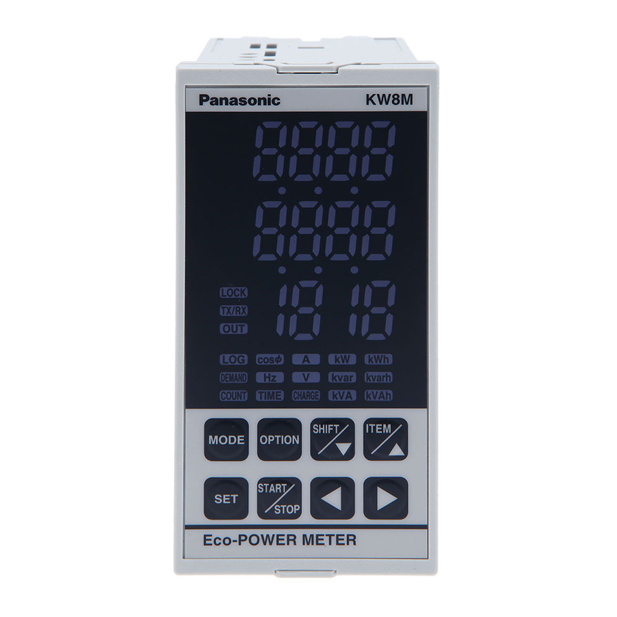
KW8M Eco-POWER METER Chapter 2 Parts Name and Working 2.1 Parts Names ①Display indicator ・Lighting or Blinking according to the display ②LOCK indicator ・Lighting while in lock mode ⑤ ③T/R indicator ・Blinking while communication ④OUT indicator ・Lighting when pulse output ②... -
Page 13: Chapter 3 Wiring
And this has no built-in power switch, circuit breaker or fuse for measured voltage input parts. Therefore it is necessary to install them in the circuit near this unit. 3) The terminal block of KW8M is designed to be wired from left. Insert wires to the terminal from the left and fasten with terminal screws. -
Page 14: Wiring Diagrams
KW8M Eco-POWER METER 3.2 Wiring Diagrams Please connect a breaker (3 to 15A) to power supply and voltage input part for safety reasons and to protect the device. Grounding the secondary side of VT (Voltage transformer) and CT (Current transformer) is not necessary with low-voltage circuit. - Page 15 KW8M Eco-POWER METER Three-phase three-wire system Two CTs are required to measure three-phase three-wire system. Back view Three-phase four-wire system Three CTs are required to measure three-phase four-wire system. Back view...
- Page 16 KW8M Eco-POWER METER ◆When measuring a load with exceed input voltage Voltage transformer (VT) is needed when you measure a load with over rated input voltage (440V). Use VT, those secondary rating is 110V. Grounding the secondary side of VT and CT is not necessary with low-voltage circuit.
- Page 17 KW8M Eco-POWER METER ◆How to attach the Current Transformer (CT) ・One current transformer (CT) is needed to measure 1P2W system. Two CTs are needed to measure a 1P3W/3P3W system. Three CTs are needed to measure a 3P4W system. Using all CT should be the same.
-
Page 18: For Input Connection
KW8M Eco-POWER METER Without Ammeter Power supply Breaker Shorted or resistor less than 0.1Ω Secondary current CT with 2nd current 5A Eco-POWER METER Dedicated CT for 5A Load 3.3 For input connection ・Contact input Use highly reliable metal plated contacts. Since the contact’s bounce time leads directly to error in the count value, use contacts with as short a bounce time as possible. -
Page 19: For Output Connection
KW8M Eco-POWER METER (Fig.B) No Good example Operating power supply Operating power supply Measured voltage input Measured voltage input Insulated Input equipment Input equipment Auto transformer transformer (sensor etc.) (sensor etc.) (+) (+) (-) (-) Eco-POWER Eco-POWER METER METER Do not use an auto-transformer. -
Page 20: Low Voltage Directive
KW8M Eco-POWER METER Recommended Cable Use the transmission cables shown below for Eco-POWER METER RS485 communication system. Conductor Insulator Cable Resistance Cable Applicable cable diameter Size Material Thickness (at 20℃) HITACHI 1.25 mm KPEV-S Max. Approx. Max.16.8Ω/km (AWG16) Polyethylene ×1P 0.5 mm... -
Page 21: Chapter 4 Settings
KW8M Eco-POWER METER Chapter 4 Settings 4.1 Operation procedure 【Basic setting to measure】 When wiring Eco-POWER METER and CT and setting mode 1 after power on, Eco-POWER Meter can measure the electric power. In order to use the other functions, set mode2, 3 and 4 according to your use. - Page 22 KW8M Eco-POWER METER Mode 2…Mode for setting of each parameter for pulse measurement Mode 3…Mode for setting of each parameter for serial communication Mode 4…Mode for setting of each parameter for optional function Mode 5…Mode for setting of calendar timer *For AKW8111H, be sure to set calendar timer (Mode 5) and initialize memory of main unit (Mode 4) before measuring.
- Page 23 KW8M Eco-POWER METER ◆Initial value list Mode 1 Mode 2 Item Initial value Item Initial value Phase/Wire system 1P2W Max. counting 2000 CT type speed Primary side current of CT Prescale 1.000 Voltage range 1.00 Current for time measurement Mode 3...
-
Page 24: Setting Mode Explanation
KW8M Eco-POWER METER 4.2 Setting Mode Explanation ■The value with under line is initial setting among each setting value. ☆Set before measurement. 4.2.1 MODE1 (Mode for setting each parameter for power measurement.) Phase/Wire system setting mode SYST Mode defines phase and wire system to measure. - Page 25 KW8M Eco-POWER METER Cutoff current setting mode CUTA Mode defines load current that does not measure (Cutoff current). Use to avoid miss-measurement by wiring or induction noise at no-load. 0.00kW is displayed for instantaneous electric power, 0.0A is displayed for current. Integral electric power is not added.
- Page 26 KW8M Eco-POWER METER Demand alarm setting mode 1 DEM1 *Only AKW8111H Mode defines the demand target value. ・It is set the range of 0.00 to 999999.99kW. Demand alarm setting mode 2 DEM2 *Only AKW8111H Mode defines the hysteresis to use for decide alarm off timing.
- Page 27 KW8M Eco-POWER METER Mode1 Setting flow chart Monitor ↓ <MODE> MODE1 display ↓<SET> Phase/Wire system setting mode Press <ITEM/△>, <SHIFT/▽> to change Single-phase 2-wire ⇔ Single-phase 3-wire ⇔ Three-phase 3-wire ⇔ Three-phase 4-wire. 1P2W 1P3W 3P3W 3P4W ↓<SET> CT type setting mode Press <ITEM/△>, <SHIFT/▽>...
- Page 28 KW8M Eco-POWER METER VT ratio setting mode Set VT ratio using <ITEM/△>, <SHIFT/▽>, < >, < >. If the VT is 440/110, set to “4.00”. ITEM Increase value △ (1.00 to 99.99) SHIFT Decrease value ▽ Shift place to set Shift place to set ↓<SET>...
- Page 29 KW8M Eco-POWER METER Unit for pulse output setting mode Press <ITEM/△>, <SHIFT/▽> to change 0.001 ⇔ 0.01 ⇔ 0.1 ⇔ 1 ⇔ 10 ⇔ 100 ⇔ AL-P(Alarm) ⇔ AL-C(Alarm) ⇔ AL-S(Alarm) ⇔ Cnt (Count output) ⇔ DEM(demand alarm)*. 0.001 0.01...
- Page 30 KW8M Eco-POWER METER Stand-by alarm setting mode 1 *It is only when “AL-S” is selected on unit for pulse output setting mode. Set a ratio (for the rated current) of current used for threshold value to judge stand-by power using <ITEM/△>, <SHIFT/▽>, < >, < >.
- Page 31 KW8M Eco-POWER METER Demand alarm setting mode 1 *Only AKW8111H Set target value for alarm using <ITEM/△>,<SHIFT/▽>,< >, < >. ITEM Increase value △ (0.00 to 999999.99) SHIFT Decrease value ▽ → after Shift place to set 1 sec. Shift place to set *In case of that “DEM1”...
-
Page 32: Mode2
KW8M Eco-POWER METER 4.2.2 MODE2 (Mode for setting of each parameter for pulse measurement) Max. counting speed setting mode Mode defines max. counting speed. ・Select from 2000Hz(2kHz)/30Hz Pre-scale setting mode PSCL Mode defines pre-scale value used for changing count value. -
Page 33: Mode3
KW8M Eco-POWER METER 4.2.3 MODE3 (Mode for setting of each parameter for serial communication (RS485)) Protocol setting mode PROT Mode defines communication protocol of main unit via serial communication (RS485). ・Select from MEWTOCOL / MODBUS(RTU). Station number setting mode Mode defines an individual station no. for each unit when two or more units communicate via serial communication (RS485). - Page 34 KW8M Eco-POWER METER Station number setting mode Set the station number using <ITEM/△>, <SHIFT/▽>, < >, < >. ITEM Increase value △ ( 1 to 99 ) SHIFT Decrease value ▽ Shift place to set Shift place to set ↓<SET>...
-
Page 35: Mode4
KW8M Eco-POWER METER 4.2.4 MODE4 (Mode for setting of each parameter for optional function) Auto-off setting mode Display LED turns off automatically when there is no key operation for a long time. ・Off time can be set the range of 0 to 99min. - Page 36 KW8M Eco-POWER METER MODE4 Setting flow chart Monitor ↓<MODE> MODE 1 display ↓<ITEM/△>3 times MODE 4 display ↓<SET> Auto-off setting mode Set auto-off time by minute using <ITEM/△>, <SHIFT/▽>, < >, < >. ITEM Increase value ( 0 to 99 min.) △...
-
Page 37: Mode5
KW8M Eco-POWER METER 4.2.5 MODE5 (Mode for setting the year, month, day and time.) Calendar timer setting mode *Only AKW8111H Mode defines the year, month, day and time. ・ Set year -> month -> date -> hour-> minute. *Do not set the false date, or it might occur a malfunction. -
Page 38: Chapter 5 Various Functions
KW8M Eco-POWER METER Chapter 5 Various Functions 5.1 LOCK mode It is the mode makes all keys unable. Use when you want to fix one of the measurement displays (For all displays). In this mode, you cannot input by any keys. -
Page 39: Output Depends On Integral Electric Power
KW8M Eco-POWER METER 5.3.1 Output depends on integral electric power Set the unit for pulse output (0.001/0.01/0.1/1/10/100kWh) and pulse output (transistor output) turns on every time when integral electric power reaches the unit. (Pulse width: about 100ms) 5.3.2 Instantaneous electric power alarm When it exceeds the setting instantaneous electric power, pulse output (transistor output) turns on in order to notice. -
Page 40: Counter Function
KW8M Eco-POWER METER 5.4 Counter function 5.4.1 Operation mode Maintain output hold count HOLD [Output] [Counting] possible ・・・ [Addition] n: Preset value (1) Output control is maintained after count-up completion and until reset. However counting is possible despite of count-up completion. -
Page 41: Simple Demand Function *Only Akw8111H
KW8M Eco-POWER METER 5.5 Simple demand function *Only AKW8111H AKW8111H has the simple demand function. The simple demand function is a function which presumes the average power for every 30 minutes time span and judges for every minute. It doesn’t support pulse input. It supports only CT input (power measurement). - Page 42 KW8M Eco-POWER METER ◆Working at power failure and at recovery <At power failure> ・It stops the demand measurement. ・The present demand, demand log and monthly max. log data will be saved by the build-in battery. <At recovery> ・When it recovers within the demand span, it will start measurement of present demand again with the condition before power failure.
-
Page 43: Chapter 6 Display Of Each Value
KW8M Eco-POWER METER Chapter 6 Display of each Value 6.1 Working of Monitor Display Turn on the power supply and it shifts displays for power monitoring mode and it for option mode by pressing <SHIFT/▽>. After selecting mode, it shifts to each measurement display in 1 second. -
Page 44: Outline For The Working Of Power Monitoring Mode Display
KW8M Eco-POWER METER 6.2 Outline for the Working of Power Monitoring Mode Display It displays measured value as below with Power Monitoring Mode. Integral electric power → → Integral Integral Integral active power reactive power apparent power <SHIFT/▽> <SHIFT/▽> ↓<ITEM/△>... -
Page 45: Integral Electric Power
KW8M Eco-POWER METER 6.2.1 Integral Electric power ・It displays the integral electric power. ・Press <SHIFT/▽> to shift active power, reactive power, apparent power. Integral active power Integral reactive power Integral apparent power (kWh) (kvarh) (kVAh) [kWh] [kvarh] [kVAh] Lighting Lighting Lighting ・Integral electric power is measured and displayed from 0.00 to 9999999.9 (kWh/kvarh/kVAh). -
Page 46: Instantaneous Electric Power
KW8M Eco-POWER METER 6.2.2 Instantaneous Electric power ・It displays the Instantaneous electric power. ・Press <SHIFT/▽> to shift active power, reactive power, apparent power. Instantaneous Instantaneous Instantaneous reactive power (kvar) active power (kW) apparent power (kVA) [kW] [kvar] [kVA] Lighting Lighting Lighting *Instantaneous reactive power is “-(minus)”... -
Page 47: Voltage
KW8M Eco-POWER METER ・Current measurement parts Eco-POWER METER measures the current as below. Display L1 (CT1) L2 (CT2) L3 (CT3) System Single-phase two-wire L1-phase current Single-phase three-wire L1(R)-phase current L2 (S)-phase current Three-phase three-wire L1(R)-phase current L2 (T)-phase current Three-phase four-wire... -
Page 48: Electricity Charge
KW8M Eco-POWER METER 6.2.5 Electricity Charge ・It displays the standard electricity charge for the integral electrical power. [CHARGE] Lighting *When the value exceeds ‘99999999’, will be displayed. 6.2.6 Power factor ・It displays the loads’ power factor. *Before start measuring, select phase and wire system according to the measured load. -
Page 49: Frequency
KW8M Eco-POWER METER 6.2.7 Frequency ・It displays the frequency. [Hz] Lighting 6.2.8 Hour meter ・It displays the load ON-time or load OFF-time measured by CT1. ・Press <SHIFT/▽> to change the load ON-time to load OFF-time. *“ON-h” and “OFF-h” display disappears after a few seconds by pressing <SHIFT/▽>. - Page 50 KW8M Eco-POWER METER *When load current is under the setting current for time measurement (HM-A), it measures as OFF-time. When load current is exceeded to the setting current for time measurement (HM-A), it measures as ON-time. Current for time measurement (HM-A) is set to under cutoff current (CUTA), all current is measured as OFF-time.
-
Page 51: Demand Display (Only For Akw8111H)
KW8M Eco-POWER METER 6.2.9 Demand display (only for AKW8111H) In the demand display, it displays each value as below. Demand power Demand setting Present demand Estimated demand < > < > < > < > value ↓ <SHIFT/▽> Ratio of estimated demand ↓... - Page 52 KW8M Eco-POWER METER ◆Ratio of estimated demand ・It displays the ratio of estimated demand. (Estimated demand:2.5kW, Demand setting value:5.0kW -> ratio of estimated demand is 50.0%.) ・It displays [----] when demand setting value is set to ”0.00kW”, when the ratio is over 999.9%, and for 1 minute after starting the demand span.
- Page 53 KW8M Eco-POWER METER ◆Demand log (D.LOG) ・It displays demand log. You can check a log data of 336 records (last 7 days). ・Press < >< > to change the time. ・Press <SET> to display demand value at time select display. Press <SET> again to return the time select display.
- Page 54 KW8M Eco-POWER METER ◆Monthly max. demand log (D.MON) ・You can check the log data for 13 months (max. 13 records). ・Press < >< > to change the month. ・Press <SET> to display demand value at time select display. Press <SET> again to return the time select display.
-
Page 55: Counter
KW8M Eco-POWER METER 6.2.10 Counter ・It displays present count value (pulse input value). *The position of decimal point for count-number and preset value is decided according to the setting at ‘Pre-scale setting mode’. (Refer to Setting Mode Explanation.) Pulse input number: 1000 Pulse input number: 1000 Prescale setting value: 1.000... -
Page 56: Outline For The Working Of Option Mode Display (Only For Akw8111H)
KW8M Eco-POWER METER 6.3 Outline for the Working of Option Mode Display (only for AKW8111H) It displays measured value as below with Option Mode. Monthly integral electric power → → Integral Integral Integral active power reactive power apparent power <SHIFT/▽>... -
Page 57: Monthly Integral Electric Power (Only For Akw8111H)
KW8M Eco-POWER METER 6.3.1 Monthly integral electric power (only for AKW8111H) ・It displays Monthly integral electric power. ・You can check a log data for 3 months (max.). ・Press <SHIFT/▽> to shift active power, reactive power, apparent power. ・Press < ><... -
Page 58: Daily Integral Electric Power (Only For Akw8111H)
KW8M Eco-POWER METER 6.3.2 Daily integral electric power (only for AKW8111H) ・It displays Daily integral electric power. ・You can check a log data for 93 days (max.). ・Press <SHIFT/▽> to shift active power, reactive power, apparent power. ・Press < ><... -
Page 59: Hourly Integral Electric Power (Only For Akw8111H)
KW8M Eco-POWER METER 6.3.3 Hourly integral electric power (only for AKW8111H) ・It displays Hourly integral electric power. ・You can check a log data for 2232 hours (max.). ・Press <SHIFT/▽> to shift active power, reactive power, apparent power. ・Press < ><... -
Page 60: Integral Electric Power (Active) For Arbitrary Period (Only For Akw8111H)
KW8M Eco-POWER METER 6.3.4 Integral electric power (active) for arbitrary period (only for AKW8111H) ・You can measure an integral electric active power for arbitrary period. ・Press <ITEM/△> to shift the display of the Integral electric active power. ([kWh] and [TIME] are lighting) ・Press <START/STOP>... -
Page 61: Chapter 7 Communications
KW8M Eco-POWER METER Chapter 7 Communications 7.1 Communication Procedures Communication starts with command transmission from the host computer (hereafter Master) and ends with the response of Eco-POWER METER (hereafter Slave). Master Slave • Response with data Command When master sends reading command, slave responds with the Data corresponding set value or current status. -
Page 62: Mewtocol Communication
KW8M Eco-POWER METER 7.3 MEWTOCOL Communication 7.3.1 Overview of MEWTOCOL-COM (RS485) ◆Command and response functions The computer sends commands (instructions) to Eco-POWER METER, and receives responses in return. This enables the computer and Eco-POWER METER to converse with each other, so that various kinds of information can be obtained and provided. -
Page 63: Data Register List
KW8M Eco-POWER METER 7.3.2 Data Register List (Common to AKW8 series) Data Name Unit Kind of data Range register DT00050 Rate 0.01 0 to 9999 Unsigned 16bit Rated A DT00060 CT type 5,50,100,250,400,600 Unsigned 16bit (rms) 1(0.001),10(0.01),100(0.1), 1000(1),10000(10),100000(100) 999 (Instantaneous electric power:... - Page 64 KW8M Eco-POWER METER Data Name Unit Range Kind of data register DT00176 Instantaneous 0.01kW 0 to 99999999 Unsigned 32bit active power DT00177 DT00178 Instantaneous 0.01kvar Signed 32bit -9999999 to 99999999 DT00179 reactive power DT00180 Instantaneous 0.01kVA 0 to 99999999 Unsigned 32bit...
- Page 65 KW8M Eco-POWER METER (Only for AKW8111H) Data Name Unit Kind of data Range register DT63189 Log data 0.1V 0 to 99999 Unsigned 32bit Voltage L1V DT63190 DT63191 Log data 0.1V Unsigned 32bit 0 to 99999 DT63192 Voltage L2V DT63193 Log data 0.1V...
-
Page 66: Error Codes
KW8M Eco-POWER METER 7.3.3 Error Codes ◇Basic procedure errors Error code Error name Explanation ・A Bcc error occurred in the command data. Bcc error ・A command message was sent that does not fit the transmission Format error format. ・A command was sent that is not supported. - Page 67 KW8M Eco-POWER METER ◆[MD]: Register or Reset data monitored (Registers the data to be monitored.) *Up to 16 points can be registered for one unit. ◇Command (Register) Data specification ① Data specification Word No. Word No. Destination % # ×10 ×10...
-
Page 68: Modbus (Rtu) Communication
KW8M Eco-POWER METER 7.4 MODBUS (RTU) Communication 7.4.1 Overview of MODBUS (RTU) ◆8-bit binary data in command is transmitted as it is. Data format Start bit : 1 bit Data bit : 8 bits *7bits is not available. Parity : No parity, Even parity, Odd parity Selectable... - Page 69 KW8M Eco-POWER METER ◇Data: Data depends on the function code. A request message from the master side is composed of data item, number of data and setting data. A response message from the slave side is composed of number of bytes, data and exception code in negative acknowledgement.
- Page 70 KW8M Eco-POWER METER <3> Reset integral electric power (0064H, 0065H:2-word) of address 1 (When setting to 0 [0000, 0000H]) ・Command Number of Slave Function Data item Number of ⇒ 3.5 idle data item to address code data characters write (01H)
-
Page 71: Data Register List
KW8M Eco-POWER METER 7.4.2 Data Register List (Common to AKW8 series) MODBUS Data item Kind of Range: Hexadecimal Name Unit Function (MEWTOCOL) data (Range: Decimal) code 0032H Unsigned 03H/ Rate 0.01 0H to 270FH (0 to 9999) (DT00050) 16bit 06H/10H... - Page 72 KW8M Eco-POWER METER (Common to AKW8 series) MODBUS Data item Kind of Range: Hexadecimal Name Unit Function (MEWTOCOL) data (Range: Decimal) code 006BH Current Unsigned 0.1A 0H to EA60H (0 to 60000) (DT00107) L1A(CT1) 16bit 006CH Current Unsigned 0.1A 0H to EA60H (0 to 60000)
- Page 73 KW8M Eco-POWER METER MODBUS Data item Kind of Range: Hexadecimal Name Unit Function (MEWTOCOL) data (Range: Decimal) code 00B4H<LSB> (DT00180) Instantaneous Unsigned 0H to 5F5E0FFH 0.01kVA 00B5H<MSB> apparent power 32bit (000 to 99999999) (DT00181) (Only for AKW8111H) MODBUS Data item...
- Page 74 KW8M Eco-POWER METER (Only for AKW8111H) MODBUS Data item Kind of Range: Hexadecimal Name Unit Function (MEWTOCOL) data (Range: Decimal) code F6CCH Log data Unsigned - Y:00H to 99H, M:01H to 12H (DT63180) (Year/Month) 16bit F6CDH Log data Unsigned -...
- Page 75 KW8M Eco-POWER METER (Only for AKW8111H) MODBUS Data item Kind of Range: Hexadecimal Name Unit Function (MEWTOCOL) data (Range: Decimal) code 0050H Unsigned 03H/ - SRAM Initialize 0H(0)<OFF>,1H(1)<ON> (DT00080) 16bit 06H/10H 0062H<LSB> Integral active (DT00098) Unsigned 0H to 3B9AC9FFH 03H/ power for arbitrary 0.01kW...
-
Page 76: Chapter 8 Battery For Memory Backup (Only For Akw8111H)
KW8M Eco-POWER METER Chapter 8 Battery for Memory Backup (only for AKW8111H) 8.1 Setting before using ・Battery is set to the unit AKW8111H, when shipping. Be sure to set the battery switch ON before starting the unit. It can back up the logging data and calendar time. -
Page 77: How To Remove
KW8M Eco-POWER METER 8.3 How to Remove When disposing the unit or replacing battery, refer to the below procedure and remove the battery. Undo wiring when disposing the unit or replacing battery. Electrical shock may occur if you touch places where high voltage is present. -
Page 78: Chapter 9 Specifications
KW8M Eco-POWER METER Chapter 9 Specifications 9.1 Main unit Rated operating voltage 100-240V AC Rated frequency 50/60Hz common Rated power consumption Allowable operating 85-264V AC (85 to 110% of rated operating voltage) voltage range Allowable momentary 10ms power-off time Ambient temperature -10 to +50℃... -
Page 79: Input Specifications
KW8M Eco-POWER METER 9.2 Input Specifications 9.2.1 Electric power input Single-phase two-wire system Single-phase three-wire system Phase and wire system (common) Three-phase three-wire system Three-phase four-wire system Single-phase two-wire : 0-440V AC (Line voltage) Single-phase three-wire : 0-220V AC (Phase voltage) -
Page 80: Pulse Output (Transistor Output) Specifications
KW8M Eco-POWER METER 9.3 Pulse output (Transistor output) Specifications Number of output point 1 point Insulation method Optical coupler Output type Open collector Output capacity 100mA 30V DC Pulse width approx. 100ms ON state voltage drop 1.5V or less OFF state leakage current 100μA or less... -
Page 81: Option Specifications (Only For Akw8111H)
KW8M Eco-POWER METER 9.5 Option Specifications (only for AKW8111H) 9.5.1 Logging Save cycle 60 minutes Integral active power, Integral reactive power, Integral Saved data apparent power Saved data Automatic Max. 2232 records (3 months) amount logging Monthly integral electric power,... -
Page 82: Self-Diagnostic Function
KW8M Eco-POWER METER 9.6 Self-diagnostic function If an error occurs, the following indication will be given. Indicator Meaning Output status To recover ERR0 CPU error Turn the power off and then on again. ERR1 Memory error* EEP-ROM life ended. Replace the unit. -
Page 83: Dedicated Current Transformer Specifications
KW8M Eco-POWER METER 9.9 Dedicated Current Transformer Specifications ●Clamp-on type Model No AKW4801B AKW4802B AKW4803B AKW4804B AKW4808C Primary side rated current 5A / 50A 100A 250A 400A 600A Secondary side rated 1.67mA / 33.3mA 125mA 200mA Current 16.7mA Transform ratio... -
Page 84: Chapter 10 Mounting
KW8M Eco-POWER METER Chapter 10 Mounting 10.1 Dimensions 10.1.1 Main unit (Unit: mm) (Clearance: ±1.0) -
Page 85: Panel Cutout
KW8M Eco-POWER METER 10.2 Panel cutout (Unit: mm) For connected mounting n=numbers of mounting units 10.3 Panel mounting 1) Insert a unit from the front of the panel. 2) Attach the mounting bracket by the holes at the top and bottom of case and secure in place with screws. -
Page 86: Revision History
KW8M Eco-POWER METER Revision History Issue Date Manual no. Content of revision August, 2007 ARCT1F440E edition October, 2007 ARCT1F440E-1 edition Correct the error June, 2008 ARCT1F440E-2 edition Product AKW8111H is added. Add the explanation of new function (Option function, Logging function etc.) - Page 87 ©...
Need help?
Do you have a question about the KW8M and is the answer not in the manual?
Questions and answers