Advertisement
Quick Links
USER GUIDE | UG:120
FlatPAC-EN™ and FlatPAC-EN MI
EN-Compliant Autoranging Switchers
Contents
Page
Overview
Standard Features
Optional Features
Part Numbering
Mechanical Considerations
Dos and Don'ts
Technical Description
Configuration Layout
"Quick Install" Instructions
Mechanical Drawings
10
12
13
20
22
24
28
1
2
2
2
3
4
4
6
7
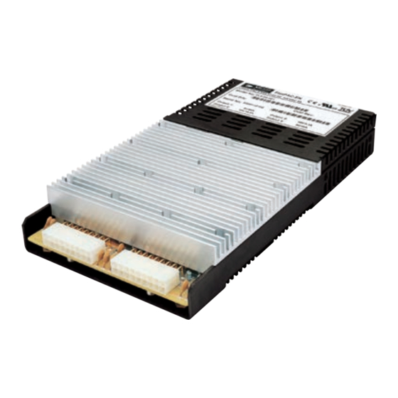
Overview
The FlatPAC-EN/EN MI is an ultra-low-profile switching power supply that provides up to 500W from
up to four isolated outputs. It operates on either 115 or 230V
It can be populated with either VI-200/VI-J00 or Maxi/Mini/Micro Vicor converters. The use of these
converters gives the FlatPAC-EN/EN MI the inherent power flexibility typical of all Vicor products. With
dimensions of 1.4in H [35,6mm] x 5.0in W [127mm] x 9.2in L [233,7mm], the FlatPAC-EN/EN MI provides
a power density greater than 7W/in
Note: The FlatPAC-EN/EN MI does not have an internal fan.
The MI version is a rugged chassis designed specifically for COTS and harsh environment applications.
nominal (47 - 63Hz), or 250 - 380V
AC
3
. It is factory configured to meet user output requirements.
UG:120
.
DC
Page 1
Advertisement

Related Manuals for VICOR FlatPAC-EN


Summary of Contents for VICOR FlatPAC-EN
-
Page 1: Table Of Contents
Thermal Curves converters gives the FlatPAC-EN/EN MI the inherent power flexibility typical of all Vicor products. With dimensions of 1.4in H [35,6mm] x 5.0in W [127mm] x 9.2in L [233,7mm], the FlatPAC-EN/EN MI provides Current Share Boards a power density greater than 7W/in . - Page 2 This feature is implemented in all converter slots (except with Micro modules). Autosense allows automatic local sensing when remote-sense connections are not made. The FlatPAC-EN™/EN MI will operate in remote-sense mode when remote-sense connections are made. Refer to Page 18 for more information on Autosense.
- Page 3 For standard mounting (conduction cooling), use A1, A2, A3, A4, B1 and B2 mounting holes. For a Vicor 2-Up FlatPAC™ retrofit replacement, use C1 and C2 as these two are identical to the recommended mounting holes on the FlatPAC. For increased ruggedness, additional mounting holes can be used to secure the power supply.
- Page 4 Technical Description The FlatPAC-EN/EN MI consists of an off-line single-phase autoranging front end, EMI filter, customer interface, power supply control circuit, associated housekeeping circuits, a MiniHAM™ module and a selection of Vicor VI-200™/VI-J00™ and/or Maxi/Mini/Micro DC-DC converters.
- Page 5 +5VS located in the interface connector. An output Enable/Disable function is provided to control Vicor DC-DC converters. If the Enable/Disable control pin is pulled low, the modules output is disabled. The nominal delay associated for an output to come up when measured from release of the Enable/Disable pin is 9 –...
- Page 6 FlatPAC-EN™/EN MI Configuration Layout UG:120 Page 6...
- Page 7 (Refer to Page 6 for more information on configuration layout and output connector type) Note: The type of output connector a FlatPAC-EN has depends on which modules are used. Also, outputs with molex connectors are limited to 9A/pin (27A per output).
- Page 8 See Page 11 for detailed diagrams of output connections. Sense Connections STUD OUTPUT CONNECTORS The FlatPAC-EN™/EN MI is shipped with Autosense installed. 10-32 STUDS (For more information on Autosense, refer to Page 18.) Sense Connections for stud outputs (only full and/or half bricks used):...
- Page 9 CBJ1-4 is the Transmit and CBJ1-5 is the Receive functions for the RS-232 command protocol. CBJ1-2 CBJ1-3 ACOK CBJ1-4 thru 9 are Enable/Disable,CBJ1-10 is General Shutdown and CBJ3-12 is +5VS. CBJ1-4 CBJ1-5 For the FlatPAC-EN™, CBJ1-2 and CBJ1-11 are not connected. CBJ1-6 E/D-4 CBJ1-7 E/D-3 CBJ1-8 E/D-2 Use Molex mating receptacle #50-57-9412 with #16-02-0097 cinch pins.
- Page 10 FlatPAC-EN™/EN MI Mechanical Drawings OUTPUT M1 OUTPUT M2 OUTPUT M1 OUTPUT M2 & M3 OUTPUTS M3 & M4 OUTPUTS M1 & M2 UG:120 Page 10...
- Page 11 USE CRIMP TOOL: MOLEX (11-01-0197) Note: The type of output connector a FlatPAC-EN has depends on which modules are used. E.g. if a two output configuration uses two half bricks (instead of a full brick and half brick) this two output configuration will have the 18 pin molex connectors, not stud connectors.
-
Page 12: Output Connectors
TERMINAL FEM CRIMP 24 – 30AWG SEL GOLD MOLEX 16-02-0097 CRIMP TOOL FOR ITEM 10 MOLEX 11-01-0209 ITEMS FOR REFERENCE ONLY (NOT INCLUDED IN KIT) FlatPAC-EN – Connector Kit listing Connector Kit 19-130044 – Available for purchase from Vicor UG:120 Page 12... -
Page 13: Interface Connections
CRIMP TOOL: MOLEX (11-01-0199) Output Power Connections There are two types of output power terminals available in the FlatPAC-EN™. Each slot has one of the following configurations: either 10-32 plated steel bolts or an 18-pin Molex connector (The type of output connector a FlatPAC-EN has depends on which modules are used. - Page 14 Power Supply to be a slave via the RS-232 interface. Operating Modes The FlatPAC-EN has two operating modes, remote and manual, which can be set using the RS-232 interface feature. The operating-mode setting is stored in a non-volatile EEPROM and requires an REON or REOFF command in order to switch modes.
- Page 15 The protocol is an ASCII character stream that will be sent back and forth between the power supply and the user. The FlatPAC-EN™/EN MI in the remote mode will be considered a slave in that it will only respond to commands and requests and will not initiate conversations. Communications are half-duplex in that only the FlatPAC-EN/EN MI receiver or transmitter may be active at one time.
- Page 16 TON1, TON2, TON3, TON4 Turn On commands for modules 1, 2, 3, or 4. These commands turn on the module identified by the trailing digit. If an automatic sequence is in effect at the time this command is received, a reply of "Inv Command" is returned; otherwise "OK"...
- Page 17 These pins should be open circuited or allowed to exceed 4.5V when enabled. Do not apply more than 5V to these inputs. Figure 4 Enable/Disable mode FlatPAC-EN™ A TTL "1" applied to the base of the transistor turns output OFF. Pin 1 (or Pin 7 for GSD) is pulled Low with respect to Signal Ground.
- Page 18 – simply hook up the outputs and the FlatPAC-EN will automatically operate in local-sense mode. To check if an output has the Autosense feature, measure the impedance from the +OUT to +SENSE and –OUT to –SENSE pins. If the impedance is 5Ω, then the output has Autosense and does not require local sense jumpers.
- Page 19 External Trim (Not applicable when using BatMod™ current source) The TRIM pin can be used for external control of the output voltage. TRIM connections on single- and dual-output connector for output M1 is J1-1 while for output M2 is J2-2. TRIM connections on triple-output connectors for output M1 is J2-6, for output M2 is J3-6 and for output M3 is J3-14.
-
Page 20: Specifications
Current Limit % of I Auto recovery See Vicor module specifications. A preload may be necessary for modules trimmed down below 90% of normal output voltage. For special and adjustable voltages, maximum setpoint accuracy is 2% of V 131% Nominal for Booster Modules. No OVP for VI-J00. - Page 21 Specifications (Cont.) (Typical at 25ºC, nominal line and 75% load unless otherwise specified.) Output (Cont.) (VI-200™/VI-J00™ Modules) Parameter Unit Notes Short-Circuit Current 20 (105 Overtemperature Limiting Not available on VI-J00 Setpoint Accuracy ±0.5 ±1 % of V See module design guide Load Regulation ±0.01 % of V...
-
Page 22: Output Power De-Rating
Output Power De-Rating FlatPAC-EN™ Output Power vs. Input Voltage Safe Safe Operating Range Operating Range Input Voltage (V FlatPAC-EN Output Power vs. DC Input Voltage Safe Operating Range Input Voltage (V UG:120 Page 22... - Page 23 Maxi Mini Micro All module configurations: The FlatPAC-EN™/EN MI or an individual output may be limited by module power limitations. One cannot exceed the output power rating of the FlatPAC-EN regardless of the module capability. Also see output power vs. input voltage charts on Page 22.
-
Page 24: Thermal Curves
Thermal Curves for FlatPAC-EN™/EN MI Output Power vs. Operating Temperature Low Line (105V ) 5V Modules Left-to-Right Air Flow Ambient Temperature (°C) 0LFM 100LFM 250LFM 500LFM 750LFM 1000LFM Output Power vs. Operating Temperature High Line (190V ) 5V Modules Left-to-Right Air Flow Ambient Temperature (°C) - Page 25 Thermal Curves for FlatPAC-EN™/EN MI (Cont.) Output Power vs. Operating Temperature Low Line (105V ) 5V Modules Right-to-Left Air Flow Ambient Temperature (°C) 0LFM 100LFM 250LFM 500LFM 750LFM 1000LFM Output Power vs. Operating Temperature High Line (190V ) 5V Modules Right-to-Left Air Flow Ambient Temperature (°C)
- Page 26 Thermal Curves for FlatPAC-EN™/EN MI (Cont.) Output Power vs. Operating Temperature Low Line (105V ) 12V Modules Left-to-Right Air Flow Ambient Temperature (°C) 0LFM 100LFM 250LFM 500LFM 750LFM 1000LFM Output Power vs. Operating Temperature High Line (190V ) 12V Modules Left-to-Right Air Flow Ambient Temperature (°C)
- Page 27 Thermal Curves for FlatPAC-EN™/EN MI (Cont.) Output Power vs. Operating Temperature Low Line (105V ) 12V Modules Right-to-Left Air Flow Ambient Temperature (°C) 0LFM 100LFM 250LFM 500LFM 750LFM 1000LFM Output Power vs. Operating Temperature High Line (190V ) 12V Modules Right-to-Left Air Flow Ambient Temperature (°C)
- Page 28 100mV conductional voltage drop in the negative return path. Constructed as a current source to drive the TRIM pin of a Vicor module, the design uses an accurate comparator circuit to monitor the power returns. In addition, the circuit is unidirectional and can only trim an output voltage up.
-
Page 29: Current Share Boards
Current Share Boards – Optional Feature (Cont.) Requirements: For proper operation, the power supplies being paralleled should be enabled at the same time. –OUT conductors must be of equal length and wire gauge. Separate –OUT conductors must be used from each supply to the load, or the use of a "Y" connection to a common point must be used as shown in Figure 8. - Page 30 Current Share Boards – Optional Feature (Cont.) 0.13" (3.3mm) Dia Non Plated thru hole 4 places Molex CT43045F surface mountable connector. .390" height above board. 1.74" 1.500" (44.2mm) (38.1mm) J1 Pinout Description Power 0.12" (3.0mm) 0.12" 0.900" (3.0mm) (22.9mm) No Connection 1.14"...
- Page 31 For more information about this or other Vicor products, or for assistance with component-based power system design, contact the Vicor office nearest you. Vicor comprehensive line of power solutions includes modular, high-density DC-DC converters and accessory components, configurable power supplies, and custom power systems. Vicor, designs and builds configurable power supplies incorporating high-density DC-DC converters and accessory components.
- Page 32 ANY AND ALL LIABILITY FOR INCLUSION AND/OR USE OF VICOR PRODUCTS IN SUCH EQUIPMENT OR APPLICATIONS AND THEREFORE SUCH INCLUSION AND/OR USE IS AT YOUR OWN RISK. Terms of Sale The purchase and sale of Vicor products is subject to the Vicor Corporation Terms and Conditions of Sale which are available at: (http://www.vicorpower.com/termsconditionswarranty) Export Control This document as well as the item(s) described herein may be subject to export control regulations.
Need help?
Do you have a question about the FlatPAC-EN and is the answer not in the manual?
Questions and answers