Advertisement
Quick Links
USER GUIDE | UG:123
DC MegaPAC
TM
DC-DC Switcher
Contents
Page
Overview
Standard Features
Optional Features
Mechanical Considerations
MegaPAC™ Dos and Don'ts
Technical Description
ConverterPAC™ Functional
Description
Configuring and Reconfiguring
MegaPACs™
Pin Identification
Mechanical Drawings
Part Numbering
Quick Install Instructions
Interface Connections
Specifications
Temperature Derating
18
1
2
2
2
3
3
5
6
7
7
8
9
11
Overview
17
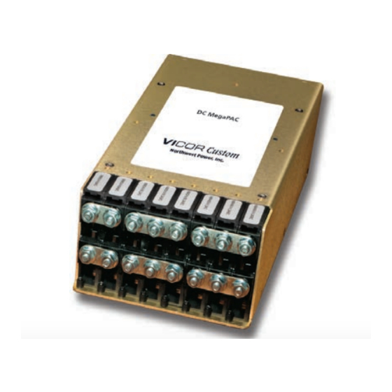
The DC MegaPAC DC-DC switcher allows users to instantly configure high efficiency power supplies.
Although small in size (6.0 x 11.7 x 3.4in) [153,4 x 296,7 x 85,8mm]), the DC MegaPAC provides up to
1600W of output power with up to 16 isolated outputs.
A complete power supply is configured by selecting and inserting up to eight slide-in output assemblies
called "ConverterPACs™." ConverterPACs incorporate one or two Vicor DC-DC converters and are
available in a wide array of outputs and power levels. The net result is a power supply that offers the
advantages of a custom supply, but is assembled from standard and modular building blocks.
The entire family of MegaPAC power supplies is completely user-configurable. If output requirements
change, i.e., more power or a different output voltage is needed, upgrading is easy: simply unlock
a single screw and replace the slide-in ModuPAC™ assembly with one that has the desired rating.
For additional flexibility, ModuPACs can be connected in parallel to increase output power (booster
ModuPACs), or in series for higher voltages. The driver is to the left of the boosters when looking at the
output end of the supply. A user-friendly interface provides control and output sequencing capability, in
addition to useful status indicators. Please consult our Applications Engineering Department if you have
other special requirements.
UG:123
®
S
C
US
C
NRT
Page 1
Advertisement

Subscribe to Our Youtube Channel
Related Manuals for VICOR DC MegaPAC


Summary of Contents for VICOR DC MegaPAC
- Page 1 Specifications The DC MegaPAC DC-DC switcher allows users to instantly configure high efficiency power supplies. Although small in size (6.0 x 11.7 x 3.4in) [153,4 x 296,7 x 85,8mm]), the DC MegaPAC provides up to Temperature Derating 1600W of output power with up to 16 isolated outputs.
- Page 2 When selecting a mounting location and orientation, the unit should be positioned so airflow is not restricted. Maintain a 2in [5,1cm] minimum clearance at both ends of the DC MegaPAC and route all cables so airflow is not obstructed. The standard unit draws air in at the fan side and exhausts air out the load side.
- Page 3 EMI/RFI emission and high efficiencies. At initial power up, the DC MegaPAC outputs are disabled to limit the inrush current and to allow the DC bus potential to charge to the operating level. A low-power flyback converter operating with PWM current-mode control converts the DC bus into regulated low voltage to power the internal housekeeping circuits and DC cooling fan.
- Page 4 General Shutdown function controls all outputs simultaneously and works in a similar manner. If driven from an electromechanical switch or relay, a capacitor should be connected to eliminate the effects of switch bounce. There is no ride-through (hold up) time available with the DC MegaPAC™. Figure 1 DC MegaPAC Architecture Under, Over &...
- Page 5 ConverterPAC™ Functional Description ConverterPACs are the family of slide-in output assemblies used in MegaPAC™ power supplies. ConverterPACs are interchangeable within a MegaPAC so they can be added, moved or changed as necessary. They are also interchangeable between different AC input MegaPAC chassis. A ConverterPAC removed from a Mini MegaPAC could be used in a three-Phase MegaPAC, for example.
- Page 6 Configuring and Reconfiguring MegaPACs™ ConverterPACs™ can be easily added, replaced or moved by sliding the assemblies in or out of a MegaPAC chassis. Most ConverterPACs are Driver ModuPACs™ and can be inserted into any available slot. For outputs greater than 200 watts, a Driver ModuPAC and one or more Booster ModuPACs will be used.
- Page 7 1&4 +VOUT Molex tool #11-01-0197. 2&5 –VOUT +Sense –Sense J1A & J1B DC MegaPAC™ Mechanical Drawings Amp 25 pin connector #746862-2 DO NOT LOOSEN OR 2 3 4 8 9 10 11 12 13 plug for flat ribbon cable. Mates with...
- Page 8 L = QPAC (VI-200) U = UniPAC™ XL = QPAC™ (VI-200) LD = DualQPAC™ (VI-J00) = DC input voltage range (only used for DC MegaPAC ConverterPACs) 0 = 12V input (10 – 20V range) 1 = 24V input (21 – 32V range) W = 24V input (18 –...
- Page 9 DC MegaPAC™ Quick Install Instructions Mounting the DC MegaPAC The DC MegaPAC can be mounted on any of four sides. Use #8-32 or M4 mounting screws. Maximum penetration should not exceed 0.15in [3,8mm]. Maintain 2in [5,1cm] clearance at either end for airflow.
- Page 10 Trim Pin Connection J2 1 Trim Pin Access 2 +Sense The Trim J2 connection should only be made if the trim option has not been installed. 3 –Sense (A “T” or an “F” in the ConverterPAC™ part number means the trim option is installed; e.g., M5V/40AT).
- Page 11 Although all outputs are open-Sense protected, the +/–Sense terminals MUST be connected to their respective outputs before the DC MegaPAC™ is powered up. Regardless of the output polarity configured, the +Sense should always connect to the +Power output. The –Sense connects to the –Power output.
- Page 12 The Enable/Disable control pins allow ConverterPAC™ outputs to be sequenced either on or off. For the DC MegaPAC™, J10-8 through 11 and J10-21 through 24 are the control pins for output positions 1 through 8. For DualPACs™, both outputs are sequenced. In parallel arrays, only the driver ConverterPAC need be controlled.
- Page 13 0V and 10V that represents the air temperature of 0 – 100°C inside the power supply. The inlet air temperature is monitored close to the fan. The driver DC MegaPAC (ModuPAC, slot #8) generates the Gate OUT signal and sends it to the booster DC MegaPAC (ModuPAC, slot #1). The Vicor zero-current switching booster technology provides for accurate, dynamic power sharing within arrays, without the need for trimming, module "matching"...
- Page 14 Auxiliary VCC +5V/0.3A (J10-16, 17) The VCC on J10-16 and J10-17 is an auxiliary 5V regulated power source (see Figure 6 and Connector Pin Identification on Page 11). It is +5V (±5%) with respect to Signal Ground, and can supply 300mA maximum.
- Page 15 Signal Ground (J3-1) Signal Ground on J3-1 is an isolated secondary ground reference for J3 status signals. It is used to provide a reference point for the Power Good circuitry and is not the same as Earth Ground on input power connector J9.
- Page 16 Figure 9 External Trim Use 22-24AWG Twisted Pair Wires (Remote Sense) +P +OUT J2-2 +Sense To Error J2-1 Load Amplifier J2-3 –Sense –P –OUT Use 22-24AWG Twisted Pair Wires Output Module VI-200/VI-J00 ≥3.3V 2.50V 10.0kΩ VI-200/VI-J00 <3.3V 0.97V 3.88kΩ Example: ±10% Trim adjust on a 12V nominal output.
- Page 17 Specifications Input Characterisitcs (10 – 20), 24V (18 – 36), 36V (21 – 56), 48V (36 – 76), Input Voltage (55 – 100) Power Factor Line Regulation 0.2% max. from 10% to full load Inrush Current 5A peak @ 48V input Conducted EMI BTR 2511, Issue 4...
- Page 18 Temperature Derating Figure 10 Temperature Derating for MegaPACs™ using 5V Current Generation ConverterPACs™ (See Curves Below for Non 5V ConverterPAC Configurations) Figure 11 Temperature Derating for MegaPACs using 5V Current Generation ConverterPACs (See Curves Above for 5V ConverterPAC Configurations) UG:123 Page 18...
- Page 19 ANY AND ALL LIABILITY FOR INCLUSION AND/OR USE OF VICOR PRODUCTS IN SUCH EQUIPMENT OR APPLICATIONS AND THEREFORE SUCH INCLUSION AND/OR USE IS AT YOUR OWN RISK. Terms of Sale The purchase and sale of Vicor products is subject to the Vicor Corporation Terms and Conditions of Sale which are available at: (http://www.vicorpower.com/termsconditionswarranty) Export Control This document as well as the item(s) described herein may be subject to export control regulations.
Need help?
Do you have a question about the DC MegaPAC and is the answer not in the manual?
Questions and answers