Asko HG9ADE1A Operating Instructions Manual
Hide thumbs
Also See for HG9ADE1A:
- Instructions for use manual (12 pages) ,
- Operating instructions manual (24 pages)
Table of Contents
Advertisement
Quick Links
Advertisement
Table of Contents

Related Manuals for Asko HG9ADE1A


Summary of Contents for Asko HG9ADE1A
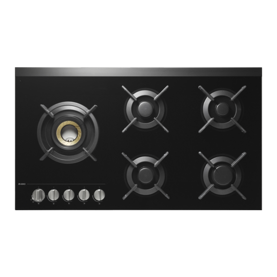
- Page 1 OPERATING INSTRUCTIONS HG1935AD / HG9ADE1A Gas Hob HG1995SD / HG9ADE1B...
-
Page 2: Table Of Contents
Contents Pictograms used ........Maintenance ..........Safety ............Daily cleaning ........................Faults ............Description ..........General ............Control knob ..........Installation ..........Use .............. Safety ............Pans ............. Preparations for installation ......Wok ring and small pan grid ......Built-in ............ -
Page 3: Pictograms Used
Pictograms used The following symbols are used throughout the manual and they have the following meanings: INFORMATION! Information, advice, tip, or recommendation WARNING! Warning general danger GAS CONNECTION! Warning gas connection ELECTRIC SHOCK! Warning danger of electric shock HOT SURFACE! Warning danger of hot surface DANGER OF FIRE! -
Page 4: Safety
Safety WARNING! READ CAREFULLY AND KEEP FOR FUTURE REFERENCE! General The manufacturer cannot be held liable for any damage resulting from failure to follow the safety instructions and warnings. Damage caused by incorrect connection, incorrect fitting, or incorrect use is not covered by the warranty. WARNING! This appliance and the accessible parts will become hot during use. - Page 5 Safety WARNING! Use only hob guards designed by the manufacturer of the cooking appliance or indicated by the appliance manufacturer in the instructions for use as suitable or hob guards incorporated in the appliance. The use of inappropriate guards can cause accidents. If a drawer underneath the appliance is permitted (see the installation instructions), without an intermediate bottom, this should not be used to store highly flammable objects/materials.
- Page 6 Safety Do not spray aerosols in the vicinity of this appliance while it is in operation. The ceramic top is extremely strong, but not unbreakable. For example, a spice jar or sharp utensil falling on it could cause it to break. WARNING! Ceramic glass plate broken Shut immediately off all burners and any electrical heating...
- Page 7 Safety WARNING! Prolonged intensive use of the appliance may call for additional ventilation, for example opening of a window, or more effective ventilation, for example increasing the level of mechanical ventilation where present. The burner components are hot during and immediately after use. Do not touch them, and avoid contact with non-heat resistant materials.
- Page 8 Safety Missing rubber feet from the pan supports can cause scratches on the drip tray or poor combustion of the burner. If the rubber feet are missing, please contact our service department.
-
Page 9: Description
Description Control knob 1. Rapid burner 2. Semi-rapid burner 3. Simmer burner 4. Wok burner 5. Pan support 6. Glass top or stainless steel drip tray 7. Wok selector ring 8. Control knob 9. Zone indication 10. 0 position 11. High setting 12. -
Page 10: Use
Pans Always ensure that the flames remain under the pan. A lot of energy is lost when flames burn around the outside of the pan. The handles could also become too hot. wrong Do not use pans with a base diameter smaller than 12 cm. Smaller pans are not as stable. -
Page 11: Burner
Burner Use the leads (1) to put together the burner parts. Wok burner position Place the wok burner in the correct way. Placing the wok burner parts incorrectly can result in a poorly functioning burner. 1. Place the burner distributor (2) in the burner housing (1). -
Page 12: Operation
Operation Ignition and adjustment The burner is fully adjustable between high and low settings. 1. Press the control knob and turn it anticlockwise. The burner will ignite. 2. Keep the control knob fully depressed for at least 3 seconds between high and low settings. The thermocouple safety pilot has been activated. -
Page 13: Maintenance
Maintenance Daily cleaning Regular maintenance after use prevents spilt food from setting too long and creating stubborn stains. Use a mild detergent for this. First clean the control knobs, burners and pan support and only then the drip tray or glass cover. This prevents the drip tray or glass cover to becoming dirty again after cleaning. -
Page 14: Faults
Faults General NOTE! If you notice a crack in the glass top (however small), switch off the hob immediately, unplug the hob, and close off the gas supply. Then contact the Service Department. Troubleshooting table If your hob does not work properly, it does not always mean that it is defective. Make sure to check the points mentioned below in the table, or visit our website for more information. - Page 15 Faults Table continued from last page Symptom Possible cause Solution Burner extinguishes after The control knob has not Keep the control knob fully depressed igniting. been depressed long or for at least 3 seconds between high deep enough (at least 3 and low settings.
-
Page 16: Installation
Installation Safety Installation, maintenance or repairs should only be carried out by professionals who are authorized by the manufacturer, as failure to do so will void the warranty. Prior to installation, ensure that the local distribution conditions (voltage, frequency, nature of the gas and gas pressure) and the adjustment of the appliance are compatible. - Page 17 Installation Do not use an adapter or an extension lead to connect the device to the electrical mains. Safe use of the device cannot be guaranteed with these accessories. Use a (flexible) cable that is flame retardant made from PVC suitable for 300/500V in a 0…70 ºC environment.
- Page 18 Installation Service Faulty parts may only be replaced by original parts. The manufacturer can only guarantee that original parts meet safety requirements. If the supply cord is damaged, it must be replaced by the manufacturer, its service agent or similarly qualified persons in order to avoid a hazard.
-
Page 19: Preparations For Installation
Installation Preparations for installation Free space around the appliance Rangehoods and exhaust fans shall be installed in accordance with manufacturers instructions. For an overhead exhaust fan A>750 mm! A (mm) B (mm) C (mm) D (mm) min. 650 min. 900 min. -
Page 20: Built-In
Installation Built-in Appliance dimensions Cut-out in the worktop Sealing tape Stainless steel drip tray Glass drip tray worktop... -
Page 21: Gas Connection
Installation Install the appliance in the worktop Gas connection metal safety hose... - Page 22 Installation Simmer Normal Large Burner Injector Adj. screw Burner rate Gas pressure burner (mm) (mm) (MJ/h) (kPa) Natural gas (NG) Simmer 0.90 0.45 4.00 Normal 1.20 0.60 6.80 Large 1.35 0.65 8.70 Wok (outer) 1.20 + 0.66 0.60 20.00 Wok (inner) 2.10 + 0.66 0.60 8.70...
-
Page 23: Connecting & Testing
Installation Connecting & testing WARNING! Check if connections are gastight. -
Page 24: Environment
Environment Environment Disposal of the appliance and packaging Sustainable materials have been used during manufacture of this appliance. This appliance must be disposed of responsibly at the end of its service life. Ask your local authorities for more information about how to do this. The appliance packaging is recyclable. -
Page 25: Your Notes
The appliance identification card is located on the bottom of the appliance. Stick the appliance identification card here. www.asko.com 861739 We reserve the right to make changes.
Need help?
Do you have a question about the HG9ADE1A and is the answer not in the manual?
Questions and answers