Advertisement
Overview of the AP3912i
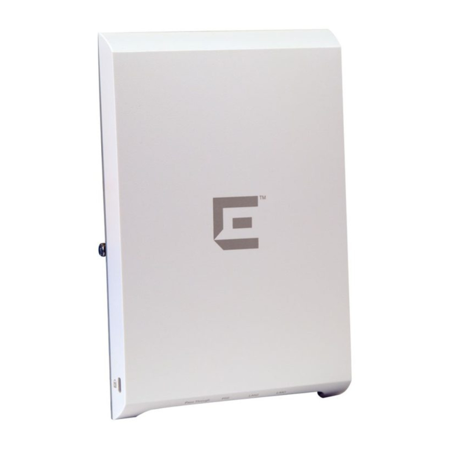
The AP3912i is a wall plate 11ac Wave 2 AP that lets you extend your Wireless LAN and deploy local Wifi while still providing extension for wired clients from the same Ethernet jack. This fully-featured access point plugs into existing Ethernet cabled wall plates. The AP provides application visibility and control and policy support over three radios and three wired LAN ports. Wireless and wired traffic can be assigned application-level policy right at the access point. The AP3912i provides flow based data handling for the wireless and wired connections in a single plug and play package. There is minimal or no impact to the existing infrastructure. The pass-through port can be used to directly expose an additional switch port from the same jack. The PSE port provides PoE (802.3af) which allows to directly power devices such as IP Phones and IP cameras. The AP3912i is designed with four single-band internal antennas for indoor use only.

Note: The AP3912i requires a minimum base firmware of 10.21.01.
The AP3912i model has the following specifications:
- Primarily designed to support wall, single and dual-gang box installation.
- Radios: Two concurrent WiFi radios (2.4 GHz and 5 GHz) and one additional radio that can operate as Bluetooth or 802.15.4.
- LEDs: 6 (Figure 2)
- Power: 802.3at (PoE+) compliant for full functionality. 802.3af is supported with reduced functionality.
- The AP3912i supports the 802.11ac and 802.11n wireless standards, with full backward compatibility with legacy 802.11abg.
- The AP3912i interoperates fully with Wireless LAN, including support for VoWLAN, branch office mode, guest services, RTLS, availability, and mobility.
- Enabled for ExtremeCloud support.
For detailed installation information about the AP3912i, see the ExtremeWireless AP3912i Installation Guide.
Uplink and Power Connections
The AP3912i uses Power over Ethernet (PoE) as follows:
Table 1 Power Sources
| Power Source | Description |
| LAN 1 - uplink PoE port | LAN 1 may be connected using an 802.3at or 802.3af switch port |
| PoE 802.3at | Power is enabled on the PSE Client port and the PSE LED is green. |
| PoE 802.3af | Power is disabled on the PSE Client port and the LED is off (not green). |
The AP has three client ports (P1. P2 and P3/PSE). These client ports let users connect wired clients, such as laptops and printers, to the network. The PSE power on P3 is enabled only if LAN 1 is powered using 802.3at.
When the PSE is enabled, 802.3af PoE devices, such as IP cameras, can be powered from P3.
The pass-through port (blue connector) in Figure 1 and Figure 4 allow direct connection to a second switch port.
The Reset button (Figure 1) is to the right of the power connections.
Note: LAN connectors with shrouds will not fit into the ports. Remove the shroud or use an optional jumper cable.

Figure 1 Power Connections and Reset Button
LEDs
LEDs are located on one side of the AP.

Figure 2 LEDs on Side of AP
 | Status |  | Radio 2 (2.4 GHz) |
 | LAN 1 (Ethernet 1) |  | PSE Client Port |
 | Radio 1 (5 GHz) |  | IoT (BLE or 802.15.4) |
Verifying the AP3912i Box Contents
Verify the contents of the box as listed in the following table:
Table 2 Contents of the AP3912i Box
| Quantity | Item |
| 1 | AP3912i Quick Reference |
| 1 | ExtremeCloud Quick Start Card |
| 1 | WS-AP3912i AP |
| 1 | Wall plate bracket (includes Security Torx captive screw) |
| The following hardware is included: | |
| 2 | Screw-in wall anchors |
| 2 | Pan-head machine screws |
| 2 | Flat-head wood screws |
| 1 | Security Torx key (size T10) |
Note: Before mounting the AP3912i, read the Safety Guidelines section.
Mounting and Connecting the AP3912i
Use these instructions as guidelines for mounting and connecting the AP3912i easily and safely.
Attach the AP3912i to an indoor wall or junction/gang box.
The wall plate bracket is included with the AP box contents.
The AP mounting bracket is designed for single and dualgang box configurations. For wider installations, you can either adapt the existing bracket or opt to wall-mount the AP.
You also have the option to additionally purchase the WSMBI-WALL05 bracket (#30521). The WALL05 bracket is designed for wall, junction/gang box, and table configurations. The WS-MBI-WALL05 bracket can be used:
- Without a hole in the wall.
- On a table.
- To physically secure the LAN cable when AP3912i is installed on a wall without a hole.
For information about WALL05 bracket configuration, see the ExtremeWireless AP3912i Installation Guide.

Figure 3 Mounting Bracket
Table 3
| Number | Description |
| 1 | AP mounting tabs |
| 2 | Security Torx captive screw |
Mounting the AP3912i to a Wall
- Using the mounting bracket (Figure 3) as a guide, choose a location where it is feasible to place the AP's center. The location must allow the LAN cables to come out of the wall within the large rectangular hole. Place the bracket against the wall. (The captive screw will be used to lock the AP in place.) Decide which two holes to use to mount the bracket. We recommend that the two holes be on opposite sides of the large center opening.
- Mark the two hole centers.
- For drywall/plasterboard walls, drill two holes using a drill bit of 1/4" or 6mm diameter.
- For drywall/plasterboard walls, screw the plastic anchors into the holes.
- Attach the wall plate bracket using the two wood screws. Torque the screw to 7.0 in-lbs.
- Connect the LAN cable from the wall and attach the AP to the mounting bracket, as described below.
Mounting to a Junction/Gang Box
- Place the bracket over the junction box with the captive screw on the left side (Figure 3) and the large, flat plate against the wall. The bracket should be attached to a vertical surface.
- Align two of the bracket holes with two of the box's holes. Use bracket holes that are closest to the center of the bracket. Make sure that the entire box is covered by the bracket.
- Using the two pan head machine screws, attach the bracket to the box using the aligned holes. Torque the screws to 9.0 in-lbs.
- Connect the power through the bracket to the AP, and attach the AP to the mounting bracket, as described below.

Figure 4 Back View
Connecting the AP to the Network
Connect the building LAN 1 wire (either PoE+ at or PoE af) to the black RJ-45 connector using short patch cables. Alternatively, connect using the associated punch-down block. The connector and punch-down block are located on the rear of the AP.
Additionally, you can connect the pass-through cable to the blue connector (top) on the back of the AP.
If you are using the punch-down block, use a punch down tool with a 110 blade. For information about pin colors, see the ExtremeWireless AP3912i Installation Guide.

Make sure that the wires are punched down professionally. Otherwise the LAN 1 link speed will be dropped to 100 Mbps, instead of 1000 Mbps.
Mounting the AP to the Bracket
- Line up the AP holes (see the arrows in Figure 4) on the rear with the two "L" shaped angled tabs near the right side of the bracket (Figure 3, item #1).
- Insert the "L" tabs into the holes and rotate the AP until it is parallel to the back of the attachment surface.
- Slide the AP approximately 1/4" to the left on the two bracket tabs.
- Attach and tighten the security torx screw (Figure 3) to the AP so that the AP is attached to the bracket. Torque the screw to 7.0 in-lbs.

Documents / ResourcesDownload manual
Here you can download full pdf version of manual, it may contain additional safety instructions, warranty information, FCC rules, etc.
Download Extreme Wireless WS-AP3912i-FCC/ROW - Access Point Quick Reference
Advertisement

Need help?
Do you have a question about the 31025 and is the answer not in the manual?
Questions and answers