
Related Manuals for NHT iWS


Summary of Contents for NHT iWS
- Page 1 In-Wall Subwoofer OWNER’S MANUAL Now Hear This 6400 Goodyear Road Benicia, CA 94510 800-NHT-9993...
-
Page 2: Table Of Contents
Parts List Enclosure Installation: New Construction (unfinished walls) Enclosure Installation: Existing Construction (retrofitting finished walls) Painting Connecting the iWS to your system Basic Settings for the X1 Crossover X1 Active Crossover X1 Design X1 Placement X1 Features and Controls X1 System Status Indicators... -
Page 3: Specifications
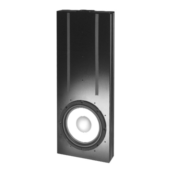
Weight: 9 lbs. Dimensions: 1.5"H x 17"W x 11.5"D Finish: matte black anodized front panel, black painted chassis iWS Enclosure In-wall subwoofer 12” aluminum cone woofer 27Hz - 140Hz, +/-3dB 86dB (2.83V at 1M) 12 ohms nominal Professional grade 5 way binding posts 36 lbs. -
Page 4: Design
Install it on a flat wall surface to ensure a good seal between the bezel and the wall. If you are using two iWS subwoofers in the same room, it is preferable to install the second subwoofer assymetrically. - Page 5 Configurations The basic configuration of the iWS can be expanded. For increased low frequency response and clarity, two iWS enclo- sures may be connected in parallel to the A1 amplifier, which is designed with enough current capability to drive two sub- woofers.
-
Page 6: Connections
The iWS is designed for use with the A1 amplifier and X1 crossover. As it does not have an internal crossover and requires these components, or it will not function properly. Proper wiring of the subwoofer is essential to good sound. At a mini- mum, 14AWG 2-conductor speaker wire is recommended for runs of 10 feet or less, with heavier special purpose speak- er wire used for longer runs. -
Page 7: Enclosure Installation
“Painting” for further instructions. 1. Locate the centerline of the studs that the iWS cabinet is to be installed between. For a 2 x 4 that is 3 5/8" deep, this will be 1 13/16" from one surface. Locate and mark this point on the inside surface of each of the two studs in at least two locations. -
Page 8: Enclosure Installation
4. Locate the centerline of the studs that the iWS cabinet is to be installed between. For a 2 x 4 that is 3 5/8" deep, this fig.3... -
Page 9: Painting
Once you have determined the vertical location of the iWS, measure 12" up from the bottom of the iWS. (Fig. 7) Make a mark on the 2 x 4 centerline at this location. Repeat for the other 2 x 4. Repeat for both 2 x 4s at a height of 24" from the bottom of the iWS. -
Page 10: Connecting The Iws To Your System
Use if: You wish to send your front L & R speakers a high-pass filtered signal AV Receiver iWS Connection Method #1 Connect the iWS from the front L & R audio signal (or surround processor and separate amplifier) Mono Line... - Page 11 You have a receiver / integrated amplifier with “Subwoofer Out” jacks AV Receiver iWS Connection Method #2 Connect the iWS from the “Subwoofer Out” and run the front L & R speakers full-range (or surround processor and separate amplifier) Mono...
-
Page 12: Basic Settings For The X1 Crossover
The subwoofer enclosure must be correctly connected to the A1 amplifier and X1 crossover in order to function properly. X1 Design The NHT X1 active crossover is designed to allow convenient front panel adjustment necessary to integrate the iWS sub- woofer with most popular satellites. It also provides unbalanced RCA and balanced XLR inputs and outputs for connec- tion with all types of receivers or separate audio components. -
Page 13: X1 Placement
Master Gain (Front Panel) The Master Gain control allows you to adjust the volume of the subwoofer relative to the other speakers in the system. Use the Master Gain judiciously. A properly calibrated subwoofer blends seamlessly with the Monitors or satellites without calling attention to itself. Here are some general... - Page 14 (as from a movie). Sources with lots of bass output will be the most useful. Adjust the LFE gain control until the bass pro- duced by the subwoofer reaches the desired level. Most users initially set the level of the LFE gain control too high, so be prepared to adjust the control over a long period of time.
- Page 15 Adjust the Low Pass Filter to approximately the same setting as the High Pass Filter as a starting point. Adjust the Low Pass Filter in small increments up or down until the blend between the Evolution Subwoofer and your main speakers is seamless and the subwoofer does not call attention to itself.
-
Page 16: X1 System Status Indicators
X1 Fine Tuning Chart The chart below was developed to assist you in the further fine tuning of your subwoofer or tower system. Should you be unable to achieve satisfactory performance from your iWS subwoofer system using the fine-tuning chart, contact your authorized NHT dealer or call our Customer Hotline at 1-800-NHT-9993 (648-9993). -
Page 17: A1 Monaural Amplifier
A1 Monaural Amplifier A1 Design The A1 is a full range (20Hz - 20kHz) audio power amplifier. It provides RCA and XLR inputs for connection with all types of receivers or separate audio components. The A1 is a single channel or monaural amplifier and can be used to drive any loudspeaker with a minimum impedance of 3 ohm. -
Page 18: A1 Power Standby Mode
Step Three: Arrange the mounting screws included with the rack ears and the plastic insulat- ing washers as shown. Step Four: Start all four screw, then tighten securely. A1 Power/Standby Mode The main power switch for the A1 is located on the rear panel and does not normally need to be used. The A1 has a stand- by mode that can be triggered internally or externally. -
Page 19: A1 - Replacing The Fuse
To reset the A1, turn the power switch (rear panel) off and then on. If the problem persists, contact your NHT dealer. -
Page 20: Limited Warranty
NHT without charge to you for parts or actual repair work.
Need help?
Do you have a question about the iWS and is the answer not in the manual?
Questions and answers