Advertisement
Quick Links
Advertisement

Summary of Contents for NHT M5
- Page 1 E v o l u t i o n O w n e r ’ s M a n u a l & S e t u p G u i d e...
-
Page 2: Important Safety Instructions
18. SERVICING - Do not attempt to service this product yourself, as opening or removing covers may expose you to dangerous voltage or other hazards. Refer all servicing to qualified service personnel. For service warranty information call the NHT Hotline number: 1-800-NHT-9993. - Page 3 T5 and T6 Tower Assembly Assembling Monitors to Pedistals Wiring Your Speakers General Guides to Wire Layout Speaker Phase Connecting Speaker Wire T5 and T6 Tower Wiring Wiring For Monaural Bass System Wiring Diagrams Connecting Evolution Electronics to Your System...
- Page 4 Evolution. If you require assistance at any time during the assembly or installation of your Evolution sys- tem, contact your authorized NHT dealer or call our Customer Hotline at 1-800-NHT-9993 (648- 9993). 1.2 Description by Model...
- Page 5 P5 - The pedestal matched to the Allows the monitor to be used free standing with separate subwoofers or placed as a rear channel speaker. P6 - The pedestal matched to the M6. Allows the monitor to be used free standing with...
- Page 6 To the right is a chart by model, indicating the various components and accessory kits includ- ed with your purchase of either the T5/T6 tower or U1/U2 subwoofer system. The M5/M6 and P5/P6 are packaged individually with their required hardware and accessories.
- Page 7 The cartons for all tower speaker components and assembly kits are color coded. The print on the 5 series cartons (M5, B5, K5, P5) is red; the print on the 6 series cartons (M6, B6, K6, P6) is blue. All other Evolution product cartons use black print.
- Page 8 2.2 Parts List M5 or M6 Monitor Carton: M5 or M6 monitor Grille carton: Grille Logo Third foot (2) Thumbscrews (2) Plastic washers (4) Rubber feet Warranty card W1 Carton: Subwoofer cabinet for the U1 System (4) Rubber feet Warranty card...
- Page 9 This section outlines the important issues to consider in configuring your system for optimum performance. The M5 and M6 monitors are designed to per- form almost identically whether placed horizon- tally or vertically. Below are some fundamental guidelines on Monitor orientation: You do not need to “toe-in”...
- Page 10 (stereo) listening. If you are not using an Evolution tower or pedestal and are orienting the monitors vertically, try to place the M5 or M6 so the tweeters are at or near ear level. Front Left 5.1 Digital Surround...
- Page 11 Subwoofer Front Right Be aware that there are other surround formats that are not covered in this setup guide. Consult your authorized NHT dealer if you are unsure about your particular system configuration. Surround Right Center Channel Front...
- Page 12 3.5 Center Channel The M5 and M6 monitors can be placed in a home entertainment center or directly on top of a TV as shown below. Remember, for proper center channel sound dispersion, the Monitor should be placed horizontally. If you intend to place your center channel on a...
- Page 13 If you have a unique placement requirement or intend to use multiple subwoofer systems, consult your authorized NHT dealer or call our Customer Service Hotline at 1-800- NHT-9993 for advice.
- Page 14 Monitor Parts Assembly Step 1: Terminal Plate Orientation The M5 and M6 are delivered with the Terminal Plate oriented for horizontal monitor placement. For vertical monitor placement, the Terminals should be rotated so that the speaker wire hangs straight down the rear of the speaker.
- Page 15 Step 3: Logo Placement The M5 and M6 are supplied with a metal NHT logo that can be attached to the grilles when the speakers are placed in the vertical position only.
- Page 16 Step5: Attaching Monitor Grilles The M5 and M6 are designed to sound best when the grilles are used (they may sound slightly bright if played without the grilles). To install them, line up the four pins on the back of the grille with the four rubber cups located in the corners of the Monitor’s front baffle.
- Page 17 T5 and T6 Tower Assembly Depending on which model you purchased, you will now need the parts contained in either the K5 or K6 assembly kit. Step 1: Installing the Stabilizer Bars The aluminum bars attach to the bottom of the bass module to provide stability for the tower system.
- Page 18 Attaching the Monitor Connection Harness The Monitor Connection Harness connects the Monitor’s speaker terminals to the terminal cup on top of the subwoofer module. This terminal cup is internally wired to the uppermost of the two terminal cups at the bottom rear of the sub- woofer module.
- Page 19 Step 6: Bass Module Orientation At this point you need to decide in which orien- tation to place the subwoofers. There are two options, woofers facing inwards or outwards as shown in the illustration. If there is going to be a large object located between the towers (a television or large piece of furniture), place the subwoofer modules so that the woofers face to the outside (away from...
- Page 20 (red to red, black to black). The cable should lay flat against the back of the monitor. Tighten the terminal nuts using the NHT wrench. Step 9: Install spikes (optional) Spikes couple the speaker to the floor, improv- ing the performance of the system.
- Page 21 4.4 Assembling Monitors On Pedestals Step 1: Install Aluminum Stabilizer Bars Carefully turn the P5 or P6 bass module upside down on a soft surface, being careful not to scratch the paint. Find the four threaded holes on the bottom of the pedestal. Gently place the stabilizer bars over the threaded holes.
- Page 22 Tighten the nuts with your NHT wrench. Remember to check for the cor- rect polarity (see section 5.2 and 5.3). Slip the speaker wire into the channel. The brackets are recessed on one side to accept the ends of the wire channel.
- Page 23 other side repeat the proce- dure. Be aware that wood or tile floors can be damaged spike’s sharp tip. Four small metal cups are included with the pedestal to fit under each spike and protect the floor. Once spikes have been mounted to the stabilizer bar, slip a cup under each spike as you gently lower the tower to the floor.
- Page 24 There are two Terminal Plates on the backside of the B5 and B6. The top terminal plate connects an M5 or M6 to your AV Receiver or amplifier. The bottom terminal plate connects a B5 or B6 to an A1 subwoofer amplifier.
- Page 25 5.5 Wiring for Monaural Bass The B5 bass modules and the dual W2 sub- woofer cabinets require one additional wiring step. The speaker wire coming from the B5 or W2 cabinets must be connected in parallel at the A1 subwoofer amplifier.
-
Page 26: Wiring Diagram
M5 / M6 Wiring Diagram From Surround Processor M5 / M6... - Page 27 U1 Wiring Diagram W1 Cabinet From X1...
- Page 28 U2 Wiring Diagram W2 Cabinet W2 Cabinet Use Dual Subwoofer Adapter From X1...
- Page 29 T5 Wiring Diagram T5 Tower Left To M5 From X1 Speaker Output Left Use Dual Subwoofer Adapter Speaker Output Right T5 Tower Right To M5 AV Receiver or Amplifier...
- Page 30 T6 Wiring Diagram T6 Tower Left To M6 From X1 Left From X1 Right Speaker Output Left Speaker Output Right T6 Tower Right To M6 Left Amp Right Amp AV Receiver or Amplifier...
- Page 31 If for some reason the methods described in this Owner’s Manual don’t work properly in your system, consult your NHT deal- er or call us at 1-800-NHT-9993 (648-9993) 6.1 Signal Connections Review the following connection method...
- Page 32 nect one of the Sub outputs on the X1 to the input on the A-1. Set the mode switch on the X1 to Mono. Note: If you are using two A1 amplifiers for stereo bass, as with the T6 tower system, set the mode switch on the X1 to Stereo and use the remaining Sub output on the X1 and connect to the input on the second A1 .
- Page 33 We recommend setting the speaker size in your AV Receiver processor or receiver to “small” when using either the M5 or M6 monitors. The “small” set- ting will prevent low bass frequencies from reaching the Monitors. The removal of the low...
- Page 34 6.2 Power Connections The X1 crossover receives power via the LL-1 power supply. (international version LL-2) The A1 amplifier receives power via the detach- able IEC style power cord. Caution: Prior to connecting the A1 amplifier to your audio system, make sure that all your other electronic equipment is turned off or unplugged.
- Page 35 LFE Gain One W1 = Mono Two W1 = Stereo Mono High Pass High Pass 50Hz Out L Out R M5 or M6 Not used in Method #1 LFE Gain Mono High Pass High Pass 50Hz Out L Out R...
- Page 36 Low Pass LFE In Phase Master Gain Boundary EQ Degrees Stereo Mono Gain High Pass Filter Hi Pass 10 dB 0 dB 110Hz 50Hz 80Hz LFE Gain High Pass High Pass Out L Out R Not used in Method #1...
- Page 37 X1 Active Crossover Design The NHT X1 active crossover is designed to provide convenient front-panel adjustment of the controls necessary to integrate the Evolution subwoofers with Evolution Monitors or other satellites. It also provides unbalanced RCA and balanced XLR inputs and outputs for connection with all types of receivers or separate audio components.
- Page 38 matically turn on when it detects an audio signal and turn off after 20 minutes with no signal. 12V Ext; the X1 can be remotely turned on or off when it detects a DC control signal from another component in your system. The exter- nal trigger will accept 5 - 24 volt (DC) signals.
- Page 39 80Hz. The 3-positon High Pass Filter is selec- table between 50Hz, 80Hz, and 110Hz to accommodate a variety of speaker sizes. If you are using Evolution monitors, the setting for this control shown is 80Hz. If using speakers other than Evolution monitors and Connection Methods 2 or 3, use the guidelines below.
- Page 40 X1 may be limited. In this case, set the Gain Switch to 10dB. Boundary EQ (Front Panel) The Boundary EQ is a feature unique to NHT Evolution products. Reflective boundaries (such as walls) reinforce a speaker’s bass output (3dB for two walls, 6dB for a corner) if the subwoofer is placed near them.
- Page 41 Should you be unable to achieve satisfactory performance from your Evolution subwoofer system using the fine-tuning chart, contact your authorized NHT dealer or call our Customer Hotline at 1-800-NHT-9993 (648- 9993). Fine Tuning Flow Chart...
- Page 42 9.0 A1 Monaural Amplifier 9.1 Design The A1 is a full range (20Hz - 20kHz) audio power amplifier. It provides RCA and XLR inputs for connection with all types of receivers or separate audio components. The A1 is a sin- gle channel or monaural amplifier and can be used with Evolution subwoofer and tower prod- ucts or to power individual Evolution monitors.
- Page 43 9.4 Power/Standby Mode The main power switch for the A1 is located on the rear panel and does not normally need to be used. The A1 has a standby mode that can be triggered internally or externally. On the rear panel of the A1 is a 3-position switch that deter- mines the trigger mode: On: The A1 is always on.
- Page 44 To reset the A1, turn the power switch (rear panel) off and then on. If the prob- lem persists, contact your NHT dealer. 9.7 Replacing the Fuse The A1 amplifier's fuse is user-serviceable.
- Page 45 10.0 Maintaining your system Your NHT Evolution speakers and electronics require minimal maintenance under normal use. The cabinet may be cleaned using a soft cloth. There is usually no need to use fluids such as cleaners or wax to clean the surface of the speakers.
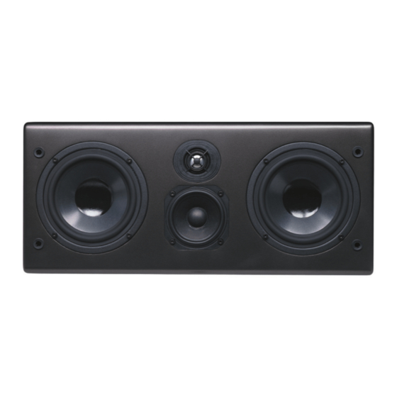
- Page 46 Both the M5 and M6, while offering different dri- ver compliments, offer similar performance. The distinguishing characteristic between the two monitors is how loud they will play; the M5 is designed for small to medium sized rooms, the M6 for large rooms. The construction methods and internal features that deliver such high per- formance are the same.
- Page 47 11.2 What is "Virtual" Focused Image Geometry? NHT's hallmark for many years was a uniquely angled cabinet which we described as having Focused Image Geometry (F.I.G.). The angled cabinet focused the mid-range and high fre-...
- Page 48 “thick”. The M5 and M6 feature a unique dual mode crossover that adjusts the monitor’s response in the mid-bass range for either placement situa- tion.
- Page 49 When com- bined with the low crossover frequency between the woofers and midrange, the resulting sound- field permits the speaker to be used in a hori- zontal or vertical orientation without significant changes in frequency response and imaging...
- Page 50 Line-Level Connection: Low level RCA/phono or XLR type connection. Load: A term used to describe the impedance that a speaker presents to an amplifier. Low-Pass Filter: A filter that passes only low frequencies below a higher limit. Main Speakers: Front L & R channel speakers, sometimes referred to as satellites.
- Page 51 er load to the acoustic power output, measured in decibels. Sub Out: An line level output for connection to a subwoofer or subwoofer signal processor. Subwoofer: A driver designed to operate over the low bass portion of the audio range. Also refers to a system consisting of a woofer and its enclosure, which are physically separate from the upper range loudspeakers.
- Page 52 What To Do 1) Check to see if your AC outlet has power. 2) X1 protection fuse may be blown and needs to be replaced. Contact your NHT dealer for assistance. 3) A1 protection fuse may be blown and needs to be replaced. See section 10.6 changing the fuse.
-
Page 53: Specifications
14.0 Specifications A1 Amplifier Frequency response: 10Hz - 65KHz +/-3.0 dB 20Hz - 20KHz +/- 0.5 dB Distortion: <0.01% 20Hz-1KHz < 0.075% 10Hz - 20Khz Power Output: 200W rms into 8 ohms at rated distortion 250W rms into 6 ohms at rated distortion 300W rms into 4 ohms at rated distortion Signal to noise ratio: 100dB (unwtd) Input Impedance: >10K ohms... - Page 54 M5 Monitor System type Woofer Midrange Tweeter Magnetic Shielding Impedance (Minimum) Impedance (Nominal) Recommended Power Power Peak Power RMS Sensitivity Crossover Frequency Crossover Slopes (dB/octave) Response -6 dB LF Cutoff Input Connectors Dimensions (HxWxD) Weight Enclosure Material: M6 Monitor System type...
- Page 55 0.75” MDF with backer Stand For M6 Monitor 27.1” x 8.25” x 14.25” 22 lbs. 0.75” MDF with backer M5 Monitor integrated with a B5 subwoofer module 43" x 7.75" x 17.25" 72 lbs. M6 Monitor integrated with a B6 subwoofer module 47.1"...
Need help?
Do you have a question about the M5 and is the answer not in the manual?
Questions and answers